My antique radio restoration logs
The AK 246 is a 6-tube broadcast band only radio. It uses 2.5 volt AC tubes typical of the early 1930's. The circuit is conventional except that it uses a separate oscillator (56) and mixer (57) tube. Perhaps this radio was designed before the 2A7 tube was available. The set has AVC, and a double tuned front end, loosely coupled. Neither the sensitivity or tone is anything special. It is basically an AA5 in performance, but the build quality is very high.
Since the radio had not been hacked excessively, and since all original components were still in place, I decided to try and retain the original top and bottom chassis appearance if possible. The radio had some unusual construction practices that I had not seen before. Most of the resistors in the radio were mounted on two round terminal boards. Most of the resistors were the "dog bone" type with cast metal ends. These are very difficult to reproduce or restore if defective.
|
|
My usual restoration procedure is to first make a complete survey of the condition of all components. The survey results guide my restoration strategy. If major and unique components are defective and cannot be restored, I may elect to sell the radio rather than restore it. I assume that all paper and electrolytic capacitors are leaky and thus should be replaced (I always "restuff" the original containers if possible).
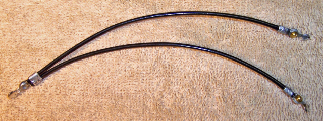
The original power cord had 3 bad places. One was in the center, one near the chassis and one near the plug. The wire was cut at the first and second bad place and spliced. Heat shrink tubing was used to insulate the individual wire splices as well as overall. The wire was then cut at the third bad place and the original plug was reinstalled at that point - resulted in only losing about 6" of the cord. The original plug was reinstalled by heating with a heat gun and pulling out the AC prongs, which retained the leads. The cord was then stripped, inserted into the plug, and the prongs reinstalled.
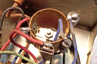
Most of the capacitors in this radio were in a metal bypass capacitor block. The can contained 11 capacitors.
 |
 |
|
Bypass Block Capacitor Before Removal |
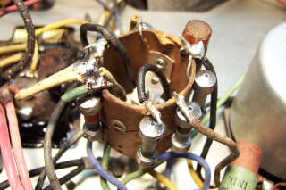
Rebuilt Bypass Block Cap |
The bypass capacitor block was rebuilt in the original case using modern components.
A pair of wire support strips which supported the
attached wiring were first removed by removing 3 rivets. The wiring was unsoldered, then the capacitor block was removed from the chassis. Per Riders, the capacitor was rated at 200 volts.
However, some caps should have a higher working voltage (such as the quality capacitor and B+ bypasses). I used 630 volt caps for all
capacitors - that's all I normally stock. To rebuild the capacitor, I had to
first unsolder the two halves of the case, since the terminal board had to be retained. The board was
originally wrapped by the paper-foil layers of the original capacitor. Once the assembly was removed from the metal case, the paper-foil layers were unwound, exposing the terminal board. New caps were soldered to both sides of the board. The bottom of the board had to be cut short to make room for 2 0.33uf/630 volt caps positioned side to side. I did not have smaller caps in stock, and 400 volt units were not significantly smaller. I had to add about 3/32" to the size of the case to make room for the larger caps.
About 14 wires connected to the capacitor. All were rubber covered. Some of the wires had to
be replaced. The green, yellow and black colors were deteriorated, but the red, blue, white
and brown were still supple and thus were left alone. Once the wires were reattached,
a wire support strips were reattached using 6-32 hardware.
The original main filter capacitor was rebuilt in its original case. First the case was cut about 1" up from the bottom by chucking the unit in my Unimat mini lathe and and scoring the case and then completing the cut with a hacksaw. This ensures a clean cut and almost invisible repair (in this case, an insulator completely hides the joint). The contents were then removed and the case cleaned. New 450 volt electrolytics were mounted inside and the case was reassembled using PVC plumbing couplings and epoxy cement. A new insulator was fashioned, since the original could not be saved. The insulator allows the negative leads of the filters to float and not contact the metal clamp which retains the capacitor. The original was 4+8 mfd. I installed a 4 and a 10mfd replacement.
Most yellow, green and black rubber covered wiring was falling apart and had to be replaced with same color cloth covered wire. All the filament wiring was replaced (black). The 1st audio grid lead was loosely wrapped with a bare stranded wire which acted as a shield. The grid lead was replaced, and the "shield" retained.
The resistance wire was OK (it measured 5 ohms on both sides of center), but the rubber insulation was crumbling and falling off. The resistor was rebuilt. The three terminal lugs were first uncrimped. The resistance wire was left attached to the center lug rivet. The resistance wire was cut at the rivets at each end lug. All the crumbling insulation was removed. A 1/16" hole was drilled in the center of the rivet in each end lug. Small black spaghetti tubing was installed over the resistance wire and crimped in the center lug. The resistance wire was then reattached to the end lugs using 0-80 brass hardware. The resistance from center lug to each end lug was then checked to ensure that the resistance was the same on both sides of the center lug. The end lugs were then crimped to secure the spaghetti tubing. Since screws were used to attach the wire, adjustments could be made if the resistance was not equal on both sides. Once the resistance was verified, the excess length of the brass screws was cut off and solder applied.
Here is the rebuilt Filament Shunt Resistor:
The 2nd AF bias resistor (300 ohms) was about 30% high. I decided it needed to be closer tolerance since it determines the bias for the type 47 output tube. I was able to hide a 1300 ohm 1/4 watt shunt resistor under the 1st detector plate choke terminal board. That lowered the resistance to 300 ohms and allowed the original resistor (a large "dog bone" type) to remain intact. The 1st detector bias resistor (2K flexible) was open. The original was a large wire wound unit, but had only 5 volts across it, or 0.0045 watts dissipation. So I was able to effectively hide a 1/4 watt carbon resistor covered with spaghetti tubing - you would have to look very hard to find it. I moved the original resistor around to make sure it would not suddenly become good or intermittent. The 1st audio plate resistor was also open. I left it in place and hid a 1/4 watt carbon resistor in spaghetti tubing behind it on one of the round terminal boards. Again, the replacement is barely visible.
The speaker and tuning capacitor were removed for access, and then chassis was then vacuumed and cleaned with GoJo and 00 steel wool as well as bottle brushes and tooth brushes. The parts were then reinstalled after replacing some rubber wiring. The tubes and tube shield were washed and dried using a heat gun and reinstalled.
The radio was powered up using a Variac while the B+ was monitored. It worked the first time. Finally, the set was aligned although there was really no changed in adjustments needed.
Here are photos of the chassis before and after restoration. Before Restoration (below):

After Restoration (below):

Top View of Chassis (below):

Front View of Radio (below):
