Atwater Kent Model 165 Restoration
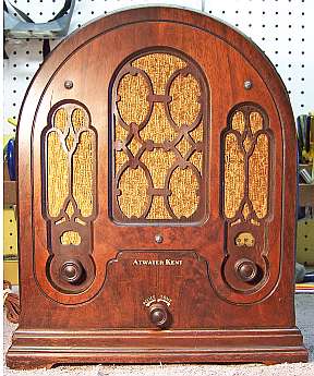 |
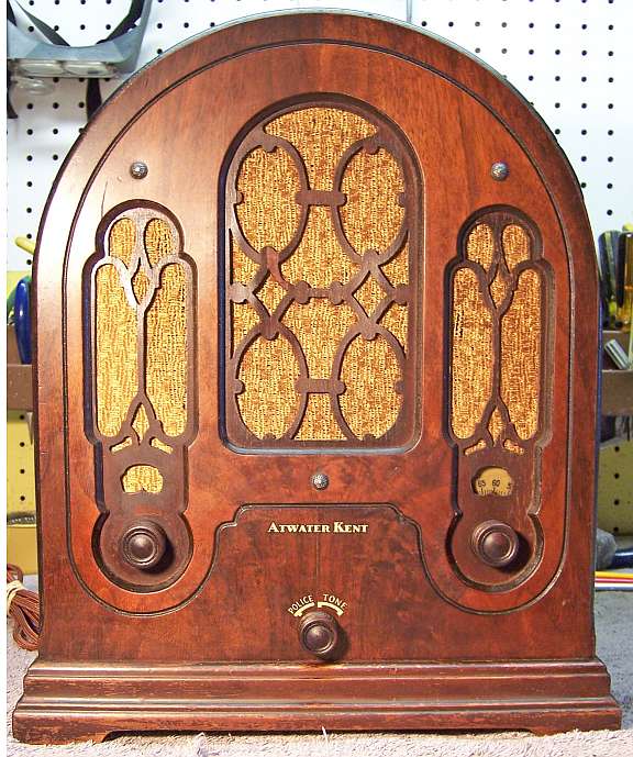
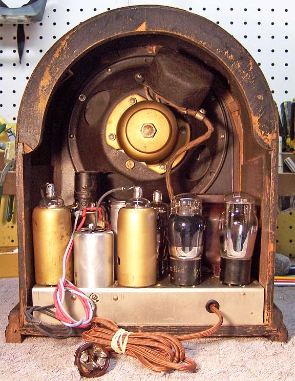
The Atwater Kent Model 165 Cathedral is a small 5-tube AC superhet circuit radio.
It receives the standard broadcast band and a "police" band.
There is no dial scale for the police band, which starts near the high end
of the
broadcast band. The radio uses 2.5 volt standard based tubes. I have owned
several of these sets in the past, but this is the ONLY ONE I have owned
with no damage to the delicate fretwork on the front. Damage is
so common that reproduction grilles are available!
The set had seen minimal servicing in the past. Basically, only
the filter capacitors had been replaced (more than ONCE - more on that
later). That being the case, I decided to try and maintain the original top and bottom chassis appearance if
possible and reverse previous repairs to the extent
possible.
The schematic for the AK165 (second type) can be found on Nostalgia
Air. Any part numbers will refer to numbers on that schematic. |
My
antique radio restoration logs
Previous Repairs
-
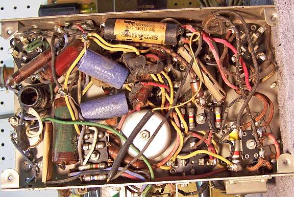
The original filter capacitor cans had been removed, and
tubular electrolytics installed under the chassis. What was weird was
that the original mounting holes had been enlarged! This suggests that
the filters had been replaced at least twice - perhaps first with screw-based can
types then with tubular electrolytics under the chassis.
-
Chassis bolts and washers were not original - replaced.
-
One tube, the type 58, was an older RCA/Cunningham brand and
likely original. All other tubes were replacements. All tubes
tested OK.
-
All the original Atwater Kent resistors and wax-paper capacitors were
intact.
-
The power cord was original (but not usable). The plug had
been replaced.
Overview
The chassis for this radio is very compact and is difficult to service. Some
components are buried beneath others that must be removed for access. Most
wiring was rubber covered and deteriorated - insulation would fall off if the
wire was moved even the slightest amount. Many of the capacitors were
multiple units with long wire leads. Replacing these with individual units
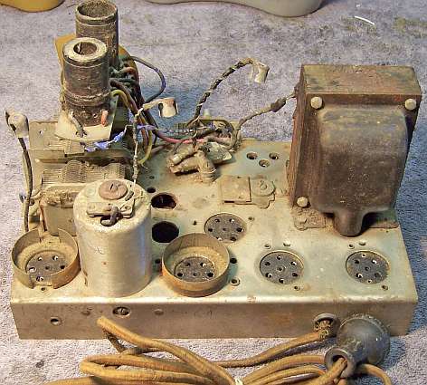
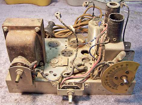
would be difficult and also very messy! The chassis was VERY dirty as
found:
Survey
My usual restoration procedure is to first make a complete
survey of the condition of all components. The survey results guide my
restoration strategy. If major and unique components are defective or
missing and
cannot be restored or replaced, I may elect to sell the radio rather than restore it.
I always assume that all paper and electrolytic capacitors are leaky and thus should be
replaced (I always "restuff" the original containers if possible).
Any mica capacitors are assumed OK until testing proves otherwise.
-
The AC power switch on the volume control was bad - dirty and/or oxidized contacts likely.
The control itself was OK after cleaning.
-
The speaker field and cone, output transformer, power transformer, and both IF transformers were good.
-
The input antenna coil T1 had an open secondary winding. The remainder
of the RF coils were OK.
-
Lots of rubber covered wire was bad - the insulation would crumble and fall
off if the wire was moved even a slight amount. Most of this wiring
would have to be replaced. This included the filament wiring from the
power transformer.
-
Eight resistors had drifted and were now out of tolerance.
-
The original filter capacitor cans had been removed in order to make room to
install tubular electrolytics under the chassis. The mounting holes
had been enlarged at some point in the past, perhaps for screw mount can
type capacitors with larger bases.
-
The power cord was original, but had several breaks and was not usable.
The plug had been replaced.
-
The dial drive speed reducer was slipping.
-
The ground lead (black) and extra long antenna leads (red) had been
removed.
Repairs
All tubes and shields were removed. Before starting repairs, I took photos of the chassis
top and bottom so that routing of wiring and component placement could be restored.
Lead dress is often critical in radios. Components were identified and
marked on the photo with a red felt-tip pen. I then removed all capacitors, documenting their locations
and connections. The volume control and band switch was removed for access
and for cleaning. The tuning capacitor and attached RF coils was
removed for cleaning access to the chassis and for repair of T1. The power
transformer was removed for replacement of some of the wiring. When I replace a component, I
always remove the original part completely from a terminal. Other
components connected at the terminal are protected from heat using old medical
clamps. Excess solder is then removed using a solder sucker in order to
expose terminal holes for reattachment of the rebuilt or replaced component.
At this point, the chassis looked like this:
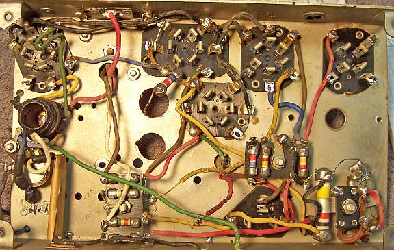
The top of the chassis was cleaned with GoJo hand cleaner and 00 steel
wool. The tuning capacitor was cleaned in an old Heathkit ultrasonic
cleaner with dilute ammonia. After drying, the bearings were lubed with
distributor cam lubricant.
Antenna Coil T1
The secondary of the antenna coil T1 was open from the tap (terminal 4A) to
the top (terminal 4). The coil was heated using a soldering pencil at the
tap location to remove some sealer. I was then lucky to find the end of
the broken upper winding. The tap (wire to terminal 4A and the top of the
lower winding) was gently raised from the coil, scraped, and tinned. The
broken wire was also scraped and tin, then joined to the tap using one strand
from a piece of stranded hookup wire. Small pieces of friction tape were
inserted between the repair and the coil, and then the repair was sealed and
secured with melted rosin from an RCA superhet catacomb chassis.
Resistors and Capacitors
All the original Atwater Kent paper capacitors were rebuilt in their original cases
using modern 630 volt film capacitors in order to maintain the original
under-chassis appearance. I reseal the cardboard tubes using rosin
salvaged from RCA catacombs (it melts at a low temperature and will not damage
the replacement capacitors). For C5 (a triple 0.05mfd) there was not
room inside the tube for three 0.047mfd 630 volt caps, so I used three 0.047mfd
100 volt radial film capacitors I had in stock. All three C5 capacitors
are used in low voltage applications (AVC filter, cathode bypass, and filament
bypass). The dual 250pf capacitors C7 and C8 were rebuilt using 220pf 500
volt mica capacitors, which JUST fit inside the tube if placed end to end (vs.
side by side). The originals were not mica, but ordinary paper/foil, and
were leaking. It is VERY important that these be rebuilt, since one has B+
on one end and the second detector diode plates on the other!
Restuffed Capacitors:

The original filter capacitors C13 and C14 were missing. However, I had
two screw base wet can type capacitors in my parts stock which were the correct
diameter (they were a bit shorter than the originals). These were
restuffed using 10mfd 450 volt capacitors. The cans were scored deeply
about 1" up from their base on my Unimat lathe, and then cut in two using a
hobby razor saw. The positive electrode was removed, retaining the
stud. The stud was cut off short and a hole drilled for a screw, nut, and
solder lug. A 10mfd 450 electrolytic was connected to the solder
lug. The negative lead, extended with bare buss wire and with insulating
sleeving, was routed through a small hole drilled in the base. After the
capacitor was mounted, the negative lead was soldered to the mounting nut.
The original positive terminal was used. The other capacitor was missing
its positive terminal. In this case, the remnants of the original positive
stud was removed and replaced by a long brass 6-32 screw, solder lugs, and fiber
insulating washers.
The large flexible resistor R3 (160 ohms) measured very high and was also
unstable (the resistance would change when the resistor terminals were moved). The
end terminals in these resistors are not soldered to the nichrome resistance
wire, since nichrome wire will not accept solder. So the terminals are
simply crimped onto the insulating core which is wound with resistance
wire. The end insulators were removed and the terminals recrimped using
needle nose pliers. The resistance was then correct and was stable as the
ends were flexed.
Most resistors in the set were cast-end dogbone types, and most were 1/3 watt
size. Several were not in tolerance and would have to be replaced.
These resistors are very difficult to reproduce. I decided to use standard
1/4 watt dogbone resistors instead (as used by Zenith and other manufacturers). But of course, any replacement
dogbone resistors would also have drifted! I collect all the dogbone
resistors I can find, and retain any out of tolerance resistors that I remove
from radios. I searched my stocks for resistors that were the correct
size, lead length, and value within 15% or so. I then repaint these
resistors with the appropriate body-end-dot color code using hobby paint.
R15 was a 50K 1.5w large cast-end dogbone resistor. It was held
in a metal clamp. In order to maintain the appearance, I decided to
rebuild it. First, the original was measured for diameter and
length. The porcelain insulator was then crushed. I was able to
remove the remaining porcelain from the ends by gently squeezing the soft metal
ends in a bench vice - not enough to deform them - just until the porcelain
inside cracked. The remnants were then removed using a variety of tools
such as small screwdrivers and nail sets. A replacement body was turned
from a piece of 3/8" dowel stock using my Unimat lathe. The diameter
was made the same as the original, since it had to be retained in a clamp.
The dowel was then drilled out its entire length to accept replacement
resistors. The original was 50K at 1.5 watts. I used 22K and 27K 1
watt film resistors in series, since there was not room for a 2 watt
resistor. This resistor is NOT critical, since it is only used as a
bleeder resistor across B+. In some AK radios I have restored, I do NOT
rebuild this resistor even if it is OPEN or a high value. The radio works
fine without it. And some versions of the chassis for this radio did NOT
have this resistor installed. The end caps were then drilled to accept the
replacement resistor leads. The body was then inserted into the caps and
secured with epoxy. The leads were bent around and soldered to the end
caps on the bottom side, so as not to be visible. The body was then
painted using hobby paint. First the body was painted flat white, then the
color stripes (yellow, red, black) were added.
Wiring
Most of the original rubber covered wiring had to be replaced. The
insulation would crumble and fall off if the wiring was moved even the slightest
amount. The power transformer was removed and covers removed in order to
replace the crumbling rubber 5-volt and 6-volt filament leads.
Other Repairs
The volume control switch was flooded with Big Bath cleaner and cycled many
times. The switch eventually worked. The bandswitch was removed
and cleaned in an old Heathkit ultrasonic cleaner. The dial drive speed
reducer was disassembled and cleaned with lacquer thinner. It was then
reassembled and greased using distributor cam lubricant. It then worked
perfectly.
Testing and Alignment
Once the radio was reassembled and the tubes installed, power was brought up
slowly using a variac. AC power consumption was monitored using a watt meter, and a
DVM monitored the B+. The radio came alive immediately and worked. The set was then aligned - no surprises. The
radio worked well and picked up lots of stations using only a 20' piece of wire
in my basement. I was also able to pick up stations on the
"police" band, including the local traffic broadcasts at 1620kHz on
the nearby interstate highway!
Restoration Results
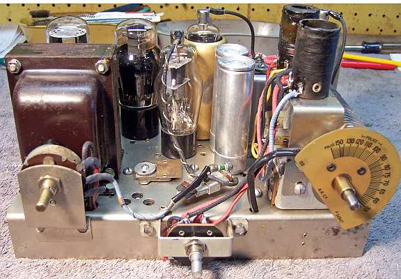
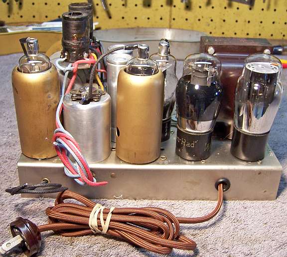
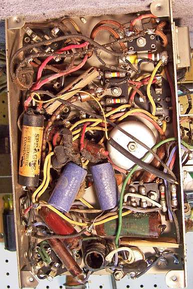
Chassis Before
|
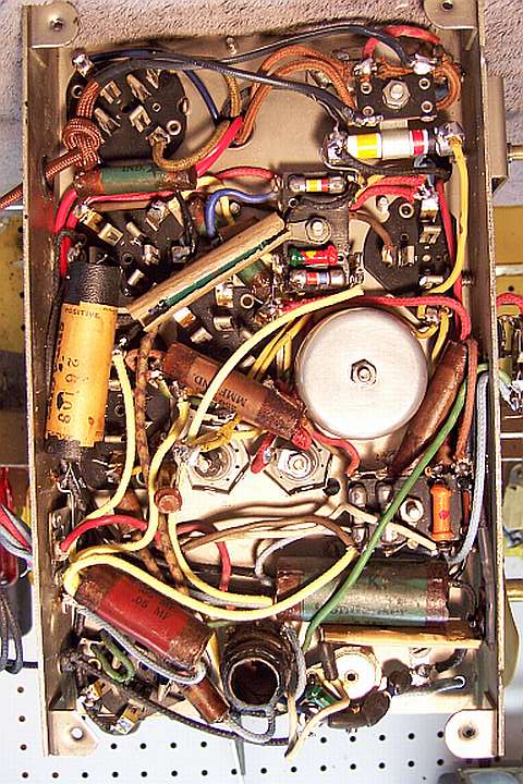
Chassis After
|
 |
 |
