The AK Model 708 is an 8-tube 4-band superhet circuit radio with AVC, circa 1934. It has an RF amplifier stage with a double-tuned pre-selector on the broadcast band (4-gang tuning capacitor), separate oscillator and mixer tubes, and two IF amplifier stages. The entire RF and IF section uses 5 type 58 tubes (Atwater Kent must have gotten a deal on type 58 tubes!) The cabinet is very compact. The chassis is also used in a console (model 808) and very similar model 808A.
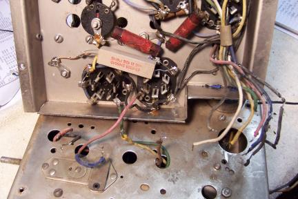
This radio is very difficult to service. All of the RF and IF circuits, with the exception of the bandswitch and coils, is on a sub-chassis that sits on top of the main chassis. This sub-chassis must be removed in order to service the RF/IF portions of the radio. There are several wires that run from the bandswitch and coils under the main chassis, through the main chassis to the sub-chassis. These leads have to be disconnected in order to remove the sub-chassis. In addition, there is a group of leads supplying B+, filament, and some signal leads that must be disconnected. Some wiring was still supple (white and red colors). Other colors were brittle and the insulation was falling off if disturbed (black, blue, green and yellow colors).
|
| Main Chassis to RF sub-chassis Interconnects with Typical Rotten Wiring! |
I always like to determine where a radio spent its life, if possible. This radio was purchased on eBay and shipped from Aguanga, CA. One replacement tube had a service shop tag from E. C. Smith Electric Shop, 614 Broadway, Seaside, Oregon dated 7/20/33 . So this was likely a West Coast radio. The cabinet finish was original and in good condition. The grille cloth and knobs were original and in good condition. Some damage was noticed in the eBay photo, and the seller ignored requests for additional photos, so I was taking somewhat of a chance. The seller also had 0 feedback.

Additional damage to the cabinet occurred during shipment due to loose or
unsecured parts and veneer. The left side of the cabinet was loose (the
glue had failed), and parts of the veneer trim was missing. Other trim parts were loose in the shipping carton and were retrieved. A piece of trim
was missing on the front top center (about 1" long). The cabinet side
was reglued to the front and clamped. Any loose pieces of veneer or trim
that could be found were then reattached to the back of the joint between the
cabinet side and front. A patch was fabricated to fill in the gap at the
top of the cabinet.
When the chassis was removed for cabinet repair and inspection, a rats nest was
found under the chassis. Luckily, only one wire was chewed in two. There was no damaged to
coils or other major components. A couple of capacitors had the ends (wax) chewed.
The radio had been extensively serviced, likely multiple times, but the repairs were older judging from the type of parts used. The radio had not been hacked extensively, and major parts were still in place. This being the case, I decided to try and retain the original top and bottom chassis appearance if possible, and reverse any previous servicing - again, if possible.
The schematic for the AK 708 can be found on Nostalgia Air. Any part numbers will refer to numbers on that schematic. While my radio has most characteristics of an AK708, it also has a few characteristics of an AK808A chassis (the AK808A is a CONSOLE). The AK708 and AK808A are VERY similar - only a few differences. But these differences explained several confusing departures from the AK708 schematic.
My usual restoration procedure is to first make a complete survey of the condition of all components. The survey results guide my restoration strategy. If major and unique components are defective or missing and cannot be restored or replaced, I may elect to sell the radio rather than restore it. I assume that all paper and electrolytic capacitors are leaky and thus should be replaced (I always "restuff" the original containers if possible). Any mica capacitors are assumed OK until testing proves otherwise.
A yellow wire from a terminal block on the main chassis, connected to the cathode of the 2A6, was found routed to the RF sub-chassis, with its end taped. I needed to find out where this wire should be connected. The wire appeared original, was in the bundle of wires going from the main chassis to the RF sub-chassis, but was NOT in the schematic. There was no obvious need to connect ANYTHING in the RF sub-chassis to the cathode of the 2A6. Also, there was an original AK single terminal block on the RF sub-chassis which was used by a previous repair person as a tie point for some resistors used to replace original AK flexible resistors. As chance would have it, I happened to glance at the schematic for an AK808A, which is VERY similar to the AK708 and AK808. In the AK808A, the single terminal block on the RF sub-chassis is used for the junction of two flexible 160 ohm resistors - one to ground and one to the 2nd IF cathode. The center tap (the single lug on the terminal block) goes to the 2A6 cathode in the main chassis. So in the AK808A, the 2nd IF and 2A6 second detector share a common cathode resistor and the 1st IF tube has its own cathode resistor. In the AK708, the 2A6 has its own cathode resistor R13 and the 1st and 2nd IF tubes share a common cathode resistor. But apparently, my chassis was initially wired as an 808A, in that the yellow wire was routed from the terminal block (2A6 cathode) to a single terminal block in the RF sub-chassis. But nothing was connected to the terminal block! The previous repair person removed the yellow wire, noting that it did nothing, and used the terminal block for a tie point! The tape was added since the other end of the yellow wire was alive.
A large resistor was found on the main chassis near the power cord entrance, but was not in schematic. The value was marked 50K, but it had drifted to 160K. It was connected from B+ to ground - just a bleeder. Again examining the schematic for the AK808A, this resistor was found - R24. So again, my chassis had some characteristics of an AK808A. It was left in place and not replaced, since its value is not critical.
I normally clean the chassis before starting restoration. I first blew off the above and below chassis dust with an air compressor. The chassis was then partially disassembled for access and cleaning. The RF sub-chassis had already been removed at this point. The tuning capacitor and dial drive mechanism were removed after unsoldering the leads and ground braids. All these parts were cleaned prior to installation.
The chassis and top components (coil shields) were cleaned using GoJo, steel wool, and toothbrushes.
In order to rebuild/restuff the metal clad multiple bypass capacitor, the contents first had to be removed.
| Ref. | Original | Replacement (all 630 volts) |
| A | .01 | .01uf |
| B | .005 | .0047 |
| C | .025 | .022 |
| E | .02 | .022 |
| F | .03 | .033 |
| H | .07 | .1 |
| J | .27 | .33 |
| K | .27 | .33 |
| L | .08 | .1 |
 |
 |
|
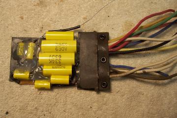
Assembled Replacement Components |
Rebuilt Multiple Bypass Capacitor |
All paper capacitors were rebuilt in their original cases using modern 630 volt film capacitors in order to maintain the original under-chassis appearance. AK capacitors are very difficult to restuff, since the outer shell is not the usual rigid cardboard tube. It is only several layers of thin paper and easily damaged. My restuffing process is as follows:
The two can type electrolytic capacitors were rebuilt in their original containers. One was original to the radio, and the other a replacement from my stock was very similar in appearance to the original. The metal cans first were scored on a Unimat lathe and the cut completed using a hobby razor saw. The cuts were near the base in both cases so that the joint would be hidden by the clamps. The original contents were removed, the cases cleaned, new 450 volt electrolytics installed inside, and the two halves of the cans joined using PVC plumbing couplings and epoxy. In both cases, the original connecting lugs were used. When the original aluminum anodes were removed, a 1" stub was retained. A hole was drilled into this stub and a solder lug attached using 4-40 hardware. The new filter capacitor (10mfd, 450 volts) was attached to this solder lug. The negative lead was routed through the side of the case and later secured by the clamp on the chassis.
Two different methods were used for restoring missing or out of tolerance cast end type dogbone resistors. For some, I found some AK originals in my parts bin that were the correct size, and that had drifted to close to the needed value (ideally lower in value, since they tend to drift higher). The existing paint markings were scraped off the body (porcelain) and the correct color bands painted on. If no original of the correct size or value was available, molded reproductions were fabricated using Syl's method archived at Radio Museum. In all cases I used 1/4 watt carbon composition or metal film resistors inside the molded body.
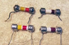 |
| Top left: Original. Top Right: Original Repainted Bottom Left and Right: Cast Reproductions |
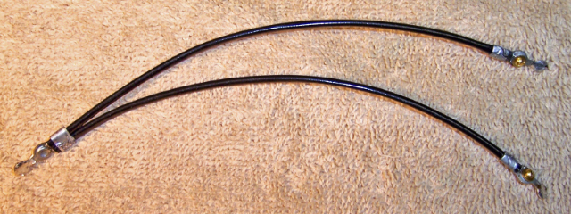
Five original AK flexible resistors had obviously failed and had been replaced by large power resistors and also carbon composition resistors. One original flexible resistor R5 remained, and was used as a model for fabricating replacements. The original resistors would have fallen apart if disturbed, since the rubber insulation was brittle. The service person used large power resistors, which were totally unnecessary due to the very low current these resistors carry. But perhaps that's all he had in the parts bin! Perhaps Atwater Kent used wire wound resistors for stability and/or to get the unusual resistance values used. Replacements were fabricated using gold plated lugs from an old data connector plug for the terminal ends. For the body I used black vinyl insulation from either #14 or #10 wire, depending on the physical size of the resistor inside. In all cases I used 1/4 watt resistors, after checking the actual current draw and needed wattage (the AK schematic shows the voltage across these resistors). Heat shrink tubing was then applied to the ends. The results are similar to the one original that remained intact in the radio.
 |
 |
|
Reproduced Flexible Resistors |
One Original Flexible Resistor. The capacitor shown does not appear in the schematic, but is an original AK 0.01mfd. It was restuffed and reinstalled. |
The resistance wire was OK (it measured 5 ohms on both sides of center), but the rubber insulation was crumbling and falling off. The resistor was rebuilt. The three terminal lugs were first uncrimped. The resistance wire was left attached to the center lug rivet. The resistance wire was cut at the rivets at each end lug. All the crumbling insulation was removed. A 1/16" hole was drilled in the center of the rivet in each end lug. Small black spaghetti tubing was installed over the resistance wire and crimped in the center lug. The resistance wire was then reattached to the end lugs using 0-80 brass hardware. The resistance from center lug to each end lug was then checked to ensure that the resistance was the same on both sides of the center lug. The end lugs were then crimped to secure the spaghetti tubing. Since screws were used to attach the wire, adjustments could be made if the resistance was not equal on both sides. Once the resistance was verified, the excess length of the brass screws was cut off and solder applied.
Here is the rebuilt Filament Shunt Resistor:
Once the radio was assembled and tubes and shields installed, power was applied using a Variac and wattmeter. The B+ was monitored using a DVM. The radio powered up normally, and all voltages were reasonable, but there was no reception. Power consumption was as expected. The audio section was working, as I could get a hum if the grid cap of the 2A6 tube was touched. Next I connected a signal generator and attempted to align the IF stages. Almost no changes were needed to the IF transformers (their adjustments were originally sealed). So the set was determined to work from the converter stage all the way to the speaker. With a 50' inside antenna connected, each band was carefully tested. Bands 1 (broadcast) and 2 (police) were totally dead. Band 3 (low short wave) worked but only in the top 20% of the dial. Band 4 (high short wave) worked normally.
Using a Realistic DX-440 digital radio with a BFO, I determined that the oscillator was not functioning except on bands 3 (high end) and 4. All voltages were reasonable, and a tube swap did not fix the problem.
I first suspected the flexible resistors R2, R3, and R4 in the oscillator section. See Flexible Resistors. I temporarily shorted out R2, the 2000 ohm resistor for the broadcast band. I then found that the high end of the broadcast band then worked down to about 1500 on the dial, although the reception was weak and the calibration was off.
I posted the issue on Antique Radio Forums, and got lots of good inputs and suggestions. Most collectors agreed that the flexible resistors were not critical, and that carbon or metal film resistors would work just fine. Some suggested wiring placement. But I did take before and after photos to make sure the wiring position was the same as the original after repairs. Some suggested adding turns to the oscillator coil feedback windings. I tried this on the first shortwave/police band coil, since it was easy to get at. It originally had about 15 turns on the winding. I added 5 more turns, being careful about the direction of winding. It made no difference. Other suggested that the rubber wiring in the RF section must be replaced. I did this on two of the bands. Again, nothing helped. I checked the fixed padder capacitor C6 for value and for leakage on my Sprague TO-4 analyzer. It had no leakage, and the value was reasonable. I even substituted a silver mica capacitor for the broadcast band. Again, no help. I removed the RF sub-chassis and double checked the wiring. No errors were found. I made dead sure the interconnects were correct.
I noted that there was only one ground connection from the tuning capacitor
to the chassis. A single wire ran from one grounding spring through the RF
sub-chassis and through the main chassis to a ground lug on the underside.
But sometime during this process, I noticed that there was measurable resistance
between the TOP and BOTTOM lugs of the oscillator stator section of the tuning
capacitor! Tightening screws holding the terminal lug to the stator plate assembly
changed the resistance. So I removed all the screws (one at a time), cleaned the
threads and under the head of each on a wire brush, cleaned the lug bracket, and
reassembled. I also cleaned where the rotor shaft contacts each brass grounding
spring as well as the spring itself with 600 grit Emory paper followed by Big
Bath cleaner. Finally, I soldered the grounding spring for the oscillator
section to the frame (it was only held by a rivet).
The radio then worked on all bands, and the dial calibration was very
close. I would have never suspected the tuning capacitor! And especially
since the capacitor had been cleaned in an ultrasonic cleaner followed by soap,
water, and a toothbrush. I have to say that this was my most challenging
restoration ever!
The radio was next aligned. There are NO trimmers for the individual bands - only a broadcast padder. The padders for the other bands are fixed. Even the IF trimmers were SEALED! The trimmers on the tuning cap obviously affect all bands. I would GUESS that they should be peaked on the top short wave band. And the broadcast padder adjusted at 600KC in the usual way. Again, I got some good suggestions on the Antique Radio Forums as well as some private messages. I eventually peaked up the tuning capacitor trimmers on the broadcast band.
The radio was very sensitive, and with its large speaker, it also had very good tone.


