Atwater Kent Model 84 Restoration

|
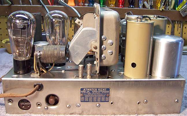
The Atwater Kent 84 (Early Version) from about 1932 is a
6-tube AC non-AVC Superhet with separate oscillator and mixer tubes. It receives only the
broadcast band. The schematic for the
model 84 is on-line at Nostalgia
Air. Another document is also needed for parts placement
and for restuffing the three metal cased bypass capacitors. That
document shows how the replacement capacitors are to be connected. http://www.nostalgiaair.org/PagesByModel/493/M0001493.pdf
The radio had seen minimal servicing in the past -
most of the original parts were still in place. I decided to try to reverse
all previous repairs to the extent
possible. However this vintage of AK receivers is difficult to
restore and maintain originality due to the unique cast end resistors and
metal can bypass capacitors used. |
My
antique radio restoration logs
Condition As Found
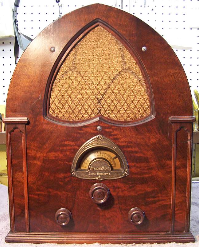
This radio was purchased at the 2011 Charlotte AWA Radio Conference. The cabinet was in
good original condition. The knobs and grille cloth were original and in good
condition. The grille insert was obviously missing (the pattern can be
seen on the grille cloth). However, there was no sign on the grille
surround that the insert was ever present! But it must have been removed
(likely were broken) and the attachment points smoothed out and somehow
refinished. The repair is invisible. I always avoid knowingly purchasing a radio
that has been restored by a collector, as many collectors take shortcuts such as removing
the original capacitors and filters. In this case, the original filter
capacitors and all tube shields were still in place. The only evidence of
repair was some tape on the grid cap leads (no new wiring obvious). The AC
plug was broken, (possibly
preventing someone from "testing" it before sales). The chassis
had a few rust pock marks, but still looked good.
Previous Repairs
-
All the tubes were ST or shouldered types. The originals
would likely have all been globe types (the sockets were labeled 280, 224
etc).
-
Several grid cap leads had been insulated using tape.
The lead from the volume control to IF amplifier grid cap had been spliced
to a new piece of wire, and the existing portion insulated with electrical
tape. There was evidence that the shield on the 2nd
IF amplifier transformer had been removed and replaced in order to insulate
the grid cap lead. Tape was also used to insulate fraying in the speaker
cable near the plug.
-
The power cord was original, but had been shortened.
-
New filter capacitors had been installed under the
chassis. Thankfully, the originals had been left in place, and terminal
strips attached to the original lugs. The new capacitors were then
installed on the terminal strips. This technique results in a totally
reversible repair! I only wish that more collectors would use this
method.
Survey
My usual restoration procedure is to first make a complete
survey of the condition of all components. The survey results guide my
restoration strategy. I never apply power to a radio before
restoration, even through a "dim bulb tester" or variac "to see
if it works". If major and unique components are defective or
missing and
cannot be restored or replaced, I may elect to sell the radio rather than restore it.
I always assume that all paper and electrolytic capacitors are leaky and thus should be
replaced (I always "restuff" the original containers if possible).
Any mica capacitors are assumed OK until testing proves otherwise.
-
The AC power switch was bad (it measured a high resistance) - dirty and/or oxidized contacts
were likely. It responded to a shot of Big Bath cleaner followed by
repeated cycling and then
worked correctly.
-
The speaker field was OK.
-
The speaker cone was perfect.
-
The output transformer was OK.
-
The power transformer checked out OK. My test procedure is to first
remove all tubes and apply about 10 volts through a fused variac and analog
wattmeter. I then check if the high voltage winding is balanced across
the center tap. An unbalance of more than about 1 volt indicates
possible shorted turns. I then raise the voltage gradually up to the
specified line voltage (110 volts) while monitoring the wattmeter. At
full voltage I check the voltage of all windings, and again check the high
voltage balance. Unloaded, a good transformer will draw less than 10
watts and each half of the high voltage should be equal within a few volts.
-
All RF coils and the IF transformers were OK. The coils used in this
radio are quite unique in construction, and difficult if not impossible to
repair. If any of them had been defective, I would have abandoned the
restoration and sold the set for parts.
-
All the RF chokes (there are several used) were OK.
-
All the tubes tested good (but all should have been globe types)
-
Some wiring in the radio was rubber covered and the insulation was falling
off. All of this wiring would have to be replaced. The
speaker cable had tape on wires near the plug, indicating fraying.
There was a break in the pilot lamp socket leads. The insulation
sleeving on the filament leads from the power transformer was brittle and
falling apart, with numerous breaks.
-
One of the wire wound bleeder resistors measured a high and changing
resistance. These resistors have a unique appearance and cannot easily
be repaired or reproduced.
-
Several cast end fixed resistors were out of tolerance.
-
The tuning dial drive rubber was functional, but did slip somewhat.
Replacements are available from Adams Manufacturing,
or in the plumbing
parts area of large hardware stores! Others have used a slice of
rubber hose from an auto parts store.
-
The volume control measured close to the correct resistance, but was likely
going to be noisy in operation. When measured using my old Knight VTVM
while rotating the shaft, there was some jumping of the pointer.
-
The original power cord had been cut short, and the AC plug was broken (not
sure if it was original).
-
All adjustment trimmers were still sealed with wax as originally shipped
from the factory.
Repairs
Before starting repairs I made BEFORE photos of the chassis bottom. I use these photos to ensure that replacement parts and
wiring are placed as close as possible to their original positions. Some
radios are subject to problems (such as oscillation) if wiring is re-routed or
lead dress is not the same as the original. The Riders Manual pages for
this radio fortunately had parts placement diagrams. And unlike original
AK documentation, parts values had been written in on the schematic. The
original documentation only contained AK part numbers - no values.
AK resistor color codes are unique and very non-standard. Servicing this radio is very difficult. The resistors are either large
wire wound units or cast end dogbone type held in insulated clamps in groups of
3-6. All the bypass capacitors were in 3 metal cans which were riveted to
the chassis! Each can held 3 or 4 capacitors.
All tubes and tube shields were removed. All non-original parts were removed. The tuning capacitor and dial
assembly was removed for
cleaning.
The top and sides of the chassis was cleaned with GoJo hand cleaner and 00 steel
wool. Since this process may leave small steel wool fragments that can cause
problems later, I follow up with a thorough vacuuming and go over everything
with a small magnet and masking tape to pick up any stray fragments. I
continue to use steel wool as I have yet to find a substitute that does as good
a job removing the "gunk".
The tuning capacitor was cleaned using a Brillo pad (external surfaces), soap,
water, and toothbrushes. It was then dried using a heat gun. I did
not attempt to disassemble the unit in order not to disturb the adjustments and
alignment. The rubber on the tuning shaft was replaced using a slice of
5/16" (inside diameter) rubber hose purchased at an auto supply
store. Although slightly smaller than the original,
it worked OK and did not slip. The hose was a very tight fit over the
knurled shaft. This caused the outside diameter to increase enough to
engage the tuning capacitor drive mechanism. In other restorations I have
used the correct part available from Adams
Manufacturing.
Insulation breaks pilot lamp wiring were repaired using shrink tubing. It
was found that the speaker cable was long enough to allow the plug to be
removed, the frayed sections cut off and stripped, and the plug
reinstalled. The original shortened power cord was retained and an old style AC plug was installed.
The filament leads from the power transformer were re-insulated using spaghetti
tubing. The leads were unsoldered from the tube sockets, the existing
insulation removed by crushing, new insulation slipped on, and the leads
reattached.
Volume Control
The volume control potentiometer showed signs of noisy operation.
The control was large and unique in appearance, and I wished to keep it
original, if possible. The resistance element is simply thin cardboard
with a thin carbon layer. This type of control CANNOT be cleaned - the
element is destroyed if contact cleaner is used. The wiper does not
directly contact the element. Rather, there is a metal ring that is
pressed against the strip as the control is rotated. I brushed off the
element using a small clean acid brush. Then I cleaned the under side of
the contact strip using lacquer thinner on a bent pipe cleaner, without
contacting the resistance element. This improved the operation
somewhat. I would have to wait until the radio was assembled and tested to
see if operation was satisfactory. A thin layer of grease on the metal
strip greatly improved smoothness of operation.
Capacitors
The original power supply filter capacitors were removed and restuffed.
The original capacitors were both 8mfd at 475 volts. I used 10mfd at 450 volts
to restuff them. I would recommend 500 or 600 volt capacitors if
available. 10mfd/500 or 600 volts and 8mfd/600 volts are (at this writing)
available from http://www.justradios.com/capacitors.html
in Canada. One capacitor had a
cardboard insulating sleeve. This sleeve was glued to the capacitor and
could not be slipped off. It was split down one side and carefully removed
(the material is VERY fragile and falls apart easily). After re-stuffing,
the sleeve was reattached using service cement. The split is visible, but
was oriented so as not to be that obvious.
The
capacitor cans were chucked in my Unimat lathe and their cases scored about 1"
from the bottom. The cuts were then completed using a hobby razor saw and
the edges cleaned up using an Exacto knife. The capacitor cans are nickel
plated copper, and are hard - not the usual aluminum. The original contents were then removed and the capacitor case
cleaned inside and out. The original positive element along with the
stud is one piece of aluminum and is difficult to remove. Diagonal cutters
were used to remove as much of the positive element as possible. The
positive lead of the replacement capacitor was extended using buss wire,
insulated using spaghetti tubing, and routed through a small hole drilled along
side the existing stud. The lead was then secured under the original
positive terminal lug (which is held to the stud using a nut and lock washer).
The negative lead of the new capacitor was extended,
insulated, and then routed though a
small hole drilled into the capacitor base near the outside and secured under
the square nut securing the capacitor in its clamp,
thus making contact with the chassis. The two halves of the case were then
joined together using a plumbing 3/4" PVC pipe coupling wrapped with
masking tape, and epoxied to each case half. The masking tape is needed
since the couplings are slightly too small in diameter. It also should
make it possible to disassemble the capacitor in the future should that be
necessary.

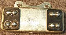
All of the bypass and coupling capacitors were in three metal cans each with three or four
capacitors inside. These cans were riveted to the chassis, and their bottom
covers were attached with solder. They don't make it easy! Obviously,
this radio was not designed with service in mind. First, all the leads had
to be identified and careful notes made as to which wire went to which
terminal. Then the rivets had to be drilled out and the capacitor removed
from the chassis. The bottom cover was then removed using a large 80 watt
soldering iron. I start on one end and remove as much solder as I can from
about 1" of the cover by simply liquefying it and then slinging the melted
solder into an old waste can. Then while heating the end and the solder is
liquid, I pry up one side with a small screwdriver. Once started, the
remainder of the solder is heated and the cover removed. I do NOT
reinstall the cover after re-stuffing with modern capacitors! The contents
can then be removed and the case cleaned of wax by heating with the large
soldering iron. The component attachment points were then cleaned of
solder and any wiring remnants. The new capacitors were then mounted to
the original attachment points and re-soldered. For replacement capacitor
connections see http://www.nostalgiaair.org/PagesByModel/493/M0001493.pdf.
I used 630 volt axial film capacitors for restuffing except in cases where a
smaller part is needed, only because that's what I stock. Radial film
capacitors are much smaller than axial, and also cheaper (and may be all that's
available in the future). In this application they are not visible!
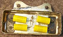
For Bypass
Capacitor #3, I used four 0.1mfd 630 volt axial film caps. The ends of all
four connect to the four lugs, and the other end of all four were soldered to
the case.
For Bypass
Capacitor #2:
For C5 I used 0.047mfd/630 volts (axial film)
For C6 I used a 0.0015mfd/630 axial film capacitor and went through my parts bin
and measured the values, picking the one closest to 0.00145 as measured on my HP
973 DVM which measures capacitance. You can likely get away with any
0.0015mfd film or mica capacitor, or use 1% mica capacitors in parallel to get
to the actual value (0.001 + 400pf plus 50pf etc.)
For C7 I used a 0.47mfd 100 volt radial film capacitor (available space is
limited). This is a low voltage capacitor and you may have to shop around to
find a 0.33mfd or 0.47mfd 50 or 100 volt capacitor small enough to fit inside
the case.
For Bypass
Capacitor #1:
For C1 and C3, I used 0.1mfd/630 volt axial film capacitors.
For C2, 0.033mfd/630 volts
For C4, 0.22mfd/400 volts (630 if it will fit!).
Any common ground leads
were soldered to the inside of the cans. The cans were then reattached to
the chassis using 8-32 round head slotted screws, nuts and lock washers salvaged from
a scrapped AK55 parts chassis.
Resistors
One of the unique cast-end resistors, the Second Detector Screen Resistor
(100K) was 30% high. The rest were either in tolerance (+/-15%) or in the
low 20's. I decided to leave these in place until the radio could be
tested. They would likely work OK. The screen resistor would have to
be replaced.
- I first took a photo of the original resistor and measurements of the
diameter and length (critical, since the resistor is retained by a clamp).
- The ceramic tube was then crushed as close as possible to the cast metal
ends.
- The remnants of the tube were then removed from the cast ends. This
is a difficult process. I used various tools such as nail sets and
ice picks to shatter the ceramic and then pick out small pieces one at a
time.
- Once the cast metal ends were clean, I center drilled a small hole in each
end to clear the leads of the replacement resistor.
- The original diameter of the ceramic tube was about 1/4", so I
decided to use an ordinary piece of 1/4" wooden dowel to replace it.
The dowel was first center drilled on a lathe to accept the 1/2 watt carbon composition
replacement resistor. While still chucked in the lathe, the
dowel was sanded and painted flat white using hobby paint, then cut to
length.
- The resistor was placed inside the wooden dowel, with its leads protruding
through the holes drilled in the cast metal ends. The wooden dowel was
then attached to the metal ends using epoxy. The resistor leads were
soldered to the metal ends at the point where original wiring leads were
attached to the resistor.
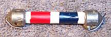
- The red and blue value stripes were then painted to match the original
resistor using hobby paint. The result is shown in the photo below.
The wire-wound bleeder resistor #2 originally measured about 12K ohms - the
marked value was 6K. Bleeder resistor #1, also 6K, was OK. I
connected a variable DC power supply to the combination of #1 and #2 (they are
in series) and ran the voltage up to about 100 volts. Then I noticed that
the voltage at the junction of the two was correct (about 1/2 the input
voltage)! And after this exercise, resistor #2 measured the correct
value. At this point I suspected a bad connection between the resistance
wire and the terminal. But the voltage was stable and did not change, even
when the resistance wire and terminal were wiggled. So at this point, I
decided to leave it alone pending the outcome of testing. This resistor
would have been impossible to replace with anything similar to its original
appearance.
Cabinet
The cabinet needed a good vacuuming inside and then cleaning on the
outside with GoJo and 00 steel wool.
Testing and Alignment
Once the radio chassis was reassembled and the tubes installed, power was brought up
slowly using a variac. AC power consumption was monitored using a watt meter, and a
DVM monitored the B+. The radio came to life immediately and worked,
but the volume was very low. I noticed that if I touched the grid cap of
the 1st detector, the volume increased greatly. The schematic does NOT agree with the wiring around the three RF transformers as
found. As found, the grid lead to the 24 first detector was
connected to the lead from the top of the #3 RF Transformer to the tuning
capacitor. The schematic shows the grid lead connected to the junction of
the #2 and #3 RF transformers (and other 80 series receivers are drawn the same
way). The RF wiring in the vicinity was rubber covered and falling
apart. When I replaced it, I originally noted that the wiring was
different from the schematic. So I used the schematic wiring (that area
had been disturbed in a previous repair to insulate a grid cap lead with tape.) When I returned the wiring to the as found condition, the set
worked great. But I never figured out why, or if there was indeed an error
in the schematic. The "double spot" trimmer was still sealed
with wax, so that could not explain the difference in performance.
All of the trimmer adjustments were sealed with wax, and the first IF
transformer adjustments are hidden under an aluminum cover with no adjustment
holes. The only accessible trimmers were the oscillator and 1st detector
grid trimmers, and the 1st detector plate trimmer (which peaks the 1st IF transformer
primary). I did not mess with the oscillator trimmer, as the dial settings
were very close. I checked the other trimmers, but there was no
improvement, so these were left alone. I did NOT adjust the first IF
trimmers. The radio is quite sensitive for
what it is - basically equivalent to an AA5 superhet in performance. The
the sound was somewhat distorted. All the voltages looked reasonable. I
did go back and trim up some of the
resistors in the 2nd detector and audio sections, since I had left unchanged some
resistors that were 20-23% high. When these resistors were trimmed to the specified
values using a resistor substitution box, no improvement resulted.
The volume control was OK - there was no scratchiness, and the operation was
smooth. The screen voltages were stable, and the two bleeder
resistors measured very close to the specified 6K ohms. So no further
action was taken.
Restoration Results
Chassis Bottom Before and After Restoration