General Electric E-101 Colorama Restoration
 |
The 1936 General Electric Model E-101 "Colorama" radio has a
rather unique visual tuning aid using red and green panel lamps which
illuminate the dial scale. The relative brightness of the red and green lamps change
depending on whether the radio is tuned to a station or not.
Colorama sets were available in both table model and console sets with
various numbers of tubes and features.
The GE Model E-101 is a large table model or upright style radio having 10 tubes. It features
all metal tubes, a large dynamic speaker and solid cabinet, 6L6 audio output stage, tuned RF stage, 2 IF stages, Automatic Frequency Control
to keep it tuned correctly, as well as the Colorama tuning feature..
The radio had seen some servicing in the past but had not been hacked excessively.
All but two of the original GE branded tubes were still in place and were
all good. A couple of paper capacitors had been replaced. A
power resistor replaced an open section of the metal-clad Candohm
resistor. The rectifier socket had been rewired to accept a 5Y3G
instead of the 5Z4.
Given that the radio was largely original, I
decided to try and retain the original top and bottom chassis appearance as much
as possible.
The schematic for the radio can be found on Nostalgia
Air. Any
references to components in this log will refer to that schematic. This was
one of the most complex restorations I have ever attempted! |
My
antique radio restoration logs
Survey
My usual restoration procedure is to first make a complete
survey of the condition of all components. The survey results guide my
restoration strategy. If major and unique components are defective and
cannot be restored or replaced, I may elect to sell the radio rather than restore it.
I assume that all paper and electrolytic capacitors are leaky and thus should be
replaced (I always "restuff" the original components if possible).
And most original resistors would have drifted and be out of tolerance range.
- The rectifier socket had been rewired and a type 5Y3G tube had been installed to replace a 5Z4.
- All tubes were good, although the metal 6L6 was very rusty (the tube runs VERY hot, and eventually melts off the paint!)
- A couple of the original paper-wax capacitors had been replaced.
- Several sections of the Candohm resistor (R5, R21, R22, R25, R26) were open. A wire wound resistor had been installed to replace an open R5 previously, but now additional sections had failed. All
remaining original carbon resistors were still in place, but about 6 had drifted
significantly in value. All were the "dogbone" type of various sizes.
- The power transformer was OK.
- The speaker field and cone were OK.
- The primary of the output transformer was OPEN.
- The primary of the saturable reactor that controls the Colorama lamps was OPEN (L27). The secondary was good (L28).
- One Colorama lamp (green) was bad - the remaining 6 were OK.
- All RF coils and IF transformers were OK.
- The original power cord (rubber) was bad.
- The power switch on the volume control was defective but likely needed only cleaning. The volume control
itself also needed cleaning.
- The tone control potentiometer was intermittent and needed
cleaning and the switch was not working. This is a very unusual type
of control in that the attached switch CLOSES at maximum clockwise
rotation. The function of this control is to cut the bass compensation
at maximum treble for short wave listening.
- Some rubber covered wiring had deteriorated and the
insulation was falling off, including most of the grid cap leads.
Cleaning
I cleaned the chassis before starting restoration.
I first blew off the above and below chassis dust with an air compressor
followed by a toothbrush and vacuum for the remaining dust.
The chassis was then partially disassembled for access and cleaning. The
Colorama lamp holder panel was removed. The
tuning capacitor and dial drive mechanism was removed. The 4 tubular filter capacitors
and the cardboard block capacitor C53/C55/C57 was removed. In order to
remove the 4 tubular filters, the Candohm resistor and several other parts
had to be removed to provide clearance for a large socket wrench to remove the
nuts. The volume
control was removed. The 4 chassis to cabinet attachment brackets were
removed. The saturable reactor L27/L28 was removed after removing the wave
trap coil and capacitor for access. This component is attached with tabs
rather than screws and getting it out without damaging the RF coils and
bandswitch was very difficult and somewhat dangerous.
The chassis and top components were cleaned using GoJo hand
cleaner, steel wool, and
toothbrushes. The shields on the IF transformers were removed for cleaning
(both the cans and the chassis underneath) and replacement of the rubber grid
cap leads. There was also one resistor inside one of the cans that was
replaced while the shield was off.
The tuning capacitor was cleaned with soap,
water, and toothbrushes and then dried using a heat gun and lubricated.
Repairs
Saturable Reactor L27/L28
My biggest restoration concern was the open primary of the saturable reactor
which controls the Colorama lamps. A good explanation of how this circuit
works can be found on Sean
Barton's web site on the GE E-91.
I had also read on Antique Radio Forums where Kim Herron had engaged Heyboer
Transformer to wind a replacement primary coil. After some investigation and
direct contact with Kim, I found that he had indeed had a replacement wound and
had some extra coils wound at the same time. I later contacted Kim and
purchased one of his coils. Kim can be contacted through Antique
Radio Forums or his web site www.goldenradioservice.com.
Once the reactor case was removed from the radio (a difficult and dangerous
task!), I found that unlike Kim's reactor, mine was POTTED IN TAR! After
removal of the cardboard cover (saved for later), the next steps were:
- Heated the reactor in an oven on aluminum foil and a metal tray, with the leads up, 250F
degrees, 1.5 hours
- Carefully removed the reactor from its case by the leads once the tar melted enough to permit removal without damage
to the lead attachments
- Cooked it another hour in the oven on aluminum foil in order to ditch as much tar as possible
- Soaked it for a day in Naphtha
- Cleaned off as much tar as possible using toothbrush and other tools
- Soaked it several more times for a day each in Naphtha, changing the cleaner each day
- Cleaned it with a clean toothbrush and other tools using Naphtha. At this point, all parts were clean.
- Removed the metal wedge between the primary coil (center coil) and
laminations using small metal ruler. This wedge is the only thing
holding the reactor together. Unlike Kim's situation, were were no
nuts and bolts holding it together.
- Once the wedge was out, I was able to coax out the top lamination and then
the remainder of the laminations, one at a time. All laminations were E type, back to back - no I sections, no gap or lacquer
obvious.
- Removed the primary and two secondary coils and did additional cleaning of coils and
laminations using Naphtha and toothbrushes
- The two secondary coils (30 ohms total) were OK. Later I had to secure
the paper wrappers on the secondary coils using hot glue (the Naphtha soak
had likely loosened the glue).
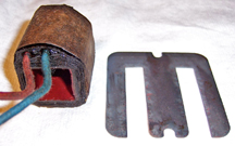 |
Shown here is the primary coil and one of the laminations. |
I then obtained a replacement primary coil from Kim Herron (wound by Heyboer
Transformer). It measured 1760 ohms - the original was 2049 ohms. I
reassembled the reactor using the replacement primary and original secondary coils
and replaced the wedge securing the assembly.
 |
Assembled reactor with replacement primary and original
secondary coils. |
The next step was to test
the reactor before installation in the radio. I used the AC lamp supply from the set's power transformer (about 30 volts
unloaded) but reduced the AC input using a Variac until the filament voltage was about 6.3.
The lamp supply was then about 24 volts. I used the two original 15 ohm resistors (R29 and R30) in the set. I reconnected the original wiring to
the lamp holder assembly and installed the Colorama lamps. I then arranged a variable DC supply for the primary or control winding, with a DVM
in series to measure the current. My reference
document gave two reference points: 11ma and 0ma. 1760 ohms at 11ma
means that the variable DC supply needed to be about 20 volts max.
I then observed lamps with 0 ma and 11 ma on the control winding.
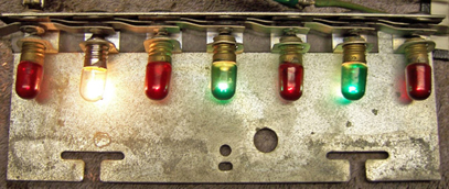 |
| With no current in the control winding, the Green lamps
were ON full and the Red lamps were dim (one burned out Green lamp was
temporarily replaced with a clear bulb for testing). |
 |
| With 11ma on the control winding, the Red lamps were ON and
the Green lamps were dim. The Red lamps peaked at about 7.5ma and
only increased slightly in brightness at 11ma. |
The reactor case was then cleaned of the remaining tar by soaking it for several days in
Naphtha and cleaning out the tar with toothbrushes and clean Naphtha. The
case, which had surface rust, was then stripped of paint and repainted. Finally, the
reactor was reinstalled in the case (the tar was NOT REPLACED!)
Colorama Lamp
One of the 7 Colorama lamps was burned out. It was green. There
were several discussions on Antique
Radio Forums discussing various ways collectors had colored replacement
lamps. The lamps themselves are normal type #40 screw based 6-8 volt
bulbs. One coloring method discussed was the Stained Glass method, which
uses various dyes for coloring stained glass - for example "Sun
Catcher" dye. I decided to go with a thermal setting type of dye
called PEBEO VITREA 160 which I purchased from dickblick.com,
a craft supplier. I chose emerald for the green bulb, and pepper red
for the red (just in case one of those burns out in the future). The dye
resulted in a close color match to the original bulbs (which had darkened
somewhat).
Candohm Resistor
Several sections of the Candohm (metal clad) resistor (R5, R21, R22, R25,
R26) were open. The R5 section had been previously jumped with an 8K
wire-wound resistor. R21 (supposedly 1K) measured 2.2K. R22 was
open. R25 and R26 (bias dropping resistors) were OK. Originally my
plans were to install the appropriate wire wound units across the open
sections. But subsequent testing showed that R21 was unstable! So I
decided to replace ALL sections (this is the recommended solution on Antique
Radio Forums). The schematic provided voltages at each terminal, so that
the required wattage in each section could be calculated (the actual wattage of
each section was unknown).
A piece of insulating material was used for the base (IIRC, salvaged from a
scrapped Tektronics Scope!). Flat head screws were countersunk in the reverse side,
and solder lugs attached to the top with nuts. Appropriate wire wound resistors were
then attached to the solder lugs. The resistor base was sized so that the
original mounting holes and screws could be used, and the spacing between solder
lugs was made close to the original so that the original set's wiring would
reach. I piece of insulating material was placed under the base to prevent
shorts to the chassis. Here is the replacement Candohm along with
the original unit:
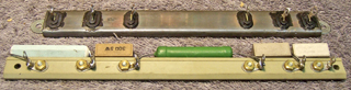
Values used were:
R5 (8.2K) 8.5K 5 watt
R21 (1K) 1K 5 watt
R22 (27K) 25K 7 watt (measured 26.22K)
R25 (30 ohms) 30 ohms 5 watt
R26 (100 ohms) 100 ohms 10 watt
Output Transformer
The original output transformer had an open primary. The voice coil
impedance was provided in the Riders documentation (5.5 ohms). From the tube manual,
the required load resistance for the 6L6 output tube is 4500 ohms. The
required ratio in the output transformer was thus 28.6:1. The closest
available transformer I could find was the Hammond 125DSE which was rated at 10
watts and 70ma DC bias and had available turns ratios of 25:1 and 35:1. This
transformer was considerably LARGER than the original, so an adaptor plate had
to be fabricated in order to mount it on the speaker. I used the 25:1
ratio, which was the closest to the original.
Capacitors
All paper capacitors were rebuilt in their original cases
using modern 630 volt film capacitors in order to maintain the original
under-chassis appearance. The non-original paper wax capacitors were
replaced with correct GE branded capacitors from my junk box (I always keep
branded capacitors such as Zenith, RCA, GE, and Philco just for this purpose,
and have also been able to collect them from Antique Radio Forums members).
The radio used 4 tubular screw based electrolytic filter capacitors.
These were all rebuilt using new parts. My standard method of rebuilding
these capacitors is:
- Mount the capacitor in my Unimat lathe and score the case about 1"
(25mm) above the screw base. I usually have to finish the cut with a hobby
razor saw - especially if the capacitor still has liquid electrolyte inside!
- The center electrode foil is removed, but the aluminum center stud is retained
and cut short. A solder lug is attached to the center stud using a
screw and nut.
- The plus lead of the replacement capacitor is attached to the solder lug.
- The negative lead of the replacement capacitor is extended through a
drilled hole in the base of the capacitor using buss wire insulated with
spaghetti tubing. The buss
wire is then loosely wrapped around the screw base and will be clamped
tightly when the capacitor is mounted.
- The two halves of the case are then reattached using PVC plumbing
couplings and epoxy. If the cut is done cleanly, the cut is hardly
visible after reassembly.
The radio also has a 3 section cardboard case electrolytic
(C53/C55/C57). This capacitor was disassembled after removing the rivets,
and the contents removed. New replacement capacitors were installed inside
and the case reassembled and secured with hot melt glue. New leads were
installed.
Dogbone Resistor Replacement
All original resistors more than 20% out of tolerance were replaced (there
were 6). I
used dogbone type resistors as were used originally. I picked out NOS and
used dogbone resistors from my stock and junk box that had drifted to the correct needed resistance and
then repainted them to match the original resistor's color codes using hobby
paint. The
replacements may continue to drift, as would most new carbon composition type
resistors. But to me, maintaining the original look is more important than
long term reliability of the radio.
Several resistors had different values than shown in the schematic.
Since the resistors appeared original, I replaced them with resistors of the
same value rather than the values shown in the schematic. Examples: R31
(120K installed vs. 220K in schematic) and R32 (330K installed, vs. 270K in
schematic).
Volume and Tone Control Repairs
The volume and tone control potentiometers were disassembled for
cleaning. I used Big Bath cleaner sold by Antique Electronic Supply.
But switches eventually worked after several rounds of spray and repeated
cycling of the switches. The resistance elements measured very high on
both units but seem to work OK in the radio. The tone control would be
impossible to replace, so I will have to live with it. The volume control
is a little scratchy on the low volume end. I would like to replace it,
but I have no idea when the correct value is, and it is also a tapped control.
Other Repairs
- All except one grid lead was rubber covered wire and falling apart - in
danger of shorting to nearby metal. They were all replaced (in order to do so I had
to remove two IF transformer shields).
- A new vinyl AC power cord was installed. A grommet was installed in
the original chassis hole to prevent damaged to the cord.
Testing
After the radio was completely reassembled, power was applied through a
wattmeter and fused Variac. Power was brought up slowly while monitoring
the B+ voltage. Normal B+ was reached with only 110 volts applied, and the
radio started working. Initial testing was done with the 6C5 Colorama tube
removed and the lamp panel disconnected in order to prevent any possible damage
to the saturable reactor or lamps. Once operation was confirmed on
all bands and control operation confirmed, the Colorama lamp assembly and 6C5
were reinstalled and tested. Next, the set was aligned.
While the Colorama lamps worked well in the assembled and aligned radio, the
results were not as good as during the standalone testing - less contrast
between lighted and darkened states. I found that the minimum AVC voltage
on the 6C5 was about -4.3 volts and not zero, and thus the current in the
reactor primary never exceeded 9.8ma (previous tested indicated that 11ma is
needed for maximum Red brightness and minimum Green). Also, the maximum
AVC voltage varied from about -8.5 to -13 volts, depending on the station tuned, and
thus the reactor primary current only went down to 3ma (so the Green bulbs were not
a maximum brightness). This was with an indoor antenna about 30' long on
the ceiling of my basement shop! And also, I am out in the country,
nowhere near a powerful AM station. Perhaps a better antenna is needed for
best results.
If the Colorama sensitivity control is placed in the LOW position (normally
used when in a metro area with powerful local stations), the lamps remained RED
at all times in my area. I may need to do further investigation as to why
my maximum AVC voltage is lower than that mentioned in Sean
Barton's web site on the GE E-91.
Since all tubes were good, all resistors checked, all capacitors replaced,
and the set carefully aligned, I feel the sensitivity is probably OK. The
set picks up 1KW stations 20-30 miles away with NO antenna connected, and
appears very sensitive. I will likely do further testing on the radio and
possibly some experimentation.
Alignment
Alignment instructions, in addition to voltages and parts locations is
contained in Riders manuals for this radio, but none of this appears on
Nostalgia Air for some reason. Alignment is straightforward except for the
3rd IF transformer secondary, which is used with a 6H6 discriminator tube to
provide Automatic Frequency Control (AFC). The AFC will pull a station
into tune if not correctly tuned to the center of the station bandwidth, and
will keep the radio tuned to the station if any component drifting occurs.
The recommended alignment procedure uses a 'scope and sweep generator that will
operate in the IF frequency range. My sweep generator only goes down to
2mhz, so that process could not be used. There is an alternative method
given in Riders which worked for me. That method beats a signal generator,
set for the frequency used to align the IFs (modulation off) loosely coupled to the first detector tube
grid lead, with a
carefully tuned radio station. The 3rd IF secondary is then carefully
tuned to zero beat with the AFC turned OFF. The AFC is then turned ON, and
if done correctly, no change in the zero beat will occur. After several
tries, I was successful in getting the AFC to work correctly.
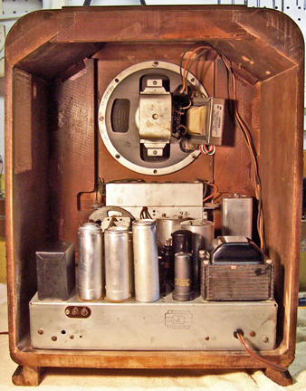
|
Chassis before restoration |
Chassis after restoration |
 |
 |
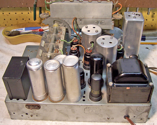 |
Rear of Chassis, After Restoration |
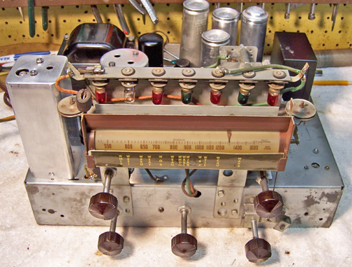 |
Front of Chassis, After Restoration |