Grunow Model 700 (Chassis 7A) Restoration
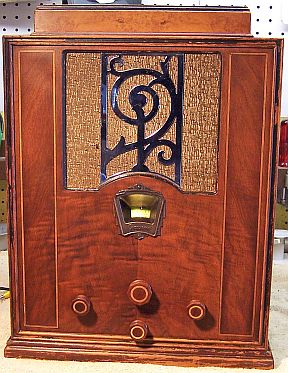 |
The Grunow (General Household Utilities) Model 700 (chassis 7A) from
circa 1934 is a 7-tube AC Superhet
circuit radio that
receives the broadcast band and one short wave band. The radio had been serviced in the past,
likely multiple times, but most
of the original
parts were still in place. I
decided to try to reverse all prior servicing and to restore the original chassis appearance if
possible. No recent restoration work had been done based on the vintage of
replacement components used.
The schematic and a parts list for the Grunow Model 700 can be found on-line on
Nostalgia
Air (there
is a separate document on alignment). There are no identifying symbols or part numbers called out in the
schematic - only values - and in the case of capacitors, the type of
container used. (tubular, block, or small can).
|
My
antique radio restoration logs
Overview
The radio was purchased on eBay and was sold as not working. Its
original cabinet finish was in excellent condition, as was the grille cloth and
chrome. The knobs were all present and original.
Servicing this radio is very difficult due to the use of a laced cable
harness. This harness blocks access to nuts and other fasteners holding
parts that must be removed for servicing. It appeared that major parts
such as the filter capacitors, filter choke, tuning capacitor and the antenna
and detector coils were attached and THEN the laced harness was installed and
connected. Many parts requiring servicing were riveted to the chassis or to coil
shields. The speaker cable was connected to the speaker using soldered
terminals, which had to be disconnected in order to remove the chassis from the
cabinet (the cable was long enough for minor servicing or alignment without
disconnecting it). Several metal cased capacitors containing multiple parts are used: one
contains 7 capacitors, one 3, one 2, and one with a single 0.05mfd capacitor
(audio coupling capacitor from the second detector to the volume control). All
of these capacitors were sealed in tar, making restuffing them quite messy and difficult.
All the small resistors used were old-style "dog bone"
types. Most were installed on a terminal board, which would have to be
unfastened from the chassis in order to change the resistors if out of
tolerance. A large wire wound Candolm type resistor was also used, having
four sections. Two of the filter capacitors, as well as the tuning
capacitor, were contained by outer shields.
The power supply is quite unusual. There are two input filter
capacitors with a normal filter choke between them. Their negative terminals
then connect to one end of the speaker field. The speaker field has a tap
which provides the negative bias to the type 42 output tube. The negative end of
the speaker field is then connected to a wire wound resistor with two taps which
provide other smaller negative bias voltages. So the power supply has
chokes (or the field coil) in both the positive and negative sides of the
supply. A final filter capacitor connects between B+ and ground.
Previous Servicing
I always attempt to avoid purchasing radios that have been
"restored" by collectors or flippers, and am looking for either all
original examples or those which have been "lightly serviced" in the
distant past by radio service shops, rather than peppered with new film
capacitors. This radio had received prior
servicing, but most of the original
parts were still in place. There was originally a dual 0.1mfd small metal can type
capacitor riveted to the top of the antenna and detector coil shields.
This capacitor had been forcibly removed, which bent and damaged the coil
shields. Remnants of the metal mounting tabs remained, along with the rivets.
This capacitor was used for the first and second AVC line filter capacitors, at
the cold ends of the antenna and first detector coils. It had been replaced by a
couple of tubular paper capacitors attached to the opposite end of the coils. This capacitor must have been a problem part.
Looking for an unrestored example for reference, a member of the Antique Radio
Forums provided a pre-restoration photo of another model 700 chassis. The
identical capacitor had been removed in his example also!
- As paper tubular capacitors were removed for restuffing, it was discovered
that almost every one had a lead cut and then resoldered to a terminal. They
had likely been disconnected for testing and re-used if not shorted or very
leaky.
- The four-section metal-clad power resistor (Candohm type) had one section
shunted by a 10K 1 watt dogbone resistor (an obvious older repair). This same
resistor in the photo provided by the Antique Radio
Forums member had two sections shunted by
newer power resistors. So this part likely also had a history of early
failure.
- One resistor (the oscillator tube grid resistor) had been replaced. The
remaining small resistors were all original.
- All of the filter capacitors were original.
- The block capacitor and all small can capacitors other than the AVC filter
capacitor were original
- Only one tube (a type 78) was branded Grunow and likely original.
The remainder were various brands such as RCA, Philco, and Tung-Sol and thus
likely were replacements. The 80 rectifier tube had been replaced by a 280 globe
type. The type 37 oscillator had been replaced by a Tung-Sol
small globe type tube marked 2-4 on the base. I was told by another
ARF member that Tung-Sol tubes of that age had the type number stamped on
the glass, and that the 2-4 on the base was only a production code. The type
number had likely been rubbed off.
- A piece of shielded cable was connected to the antenna terminal, and the
shield soldered to the chassis on the inside.
- The power plug appeared to have been replaced. The cord was original
but in bad shape.
- The schematic called for a 35K resistor in the local oscillator plate
circuit. My chassis had a 60K and 100K resistor in parallel - both old style
1 watt dogbone types. The comparison chassis photo showed a single 35K
1 watt dogbone resistor. I was not able to tell if my radio was
original or not, so I left it as it was.
Cleaning
The chassis was very dusty, but not rusty. All tubes and tube
shields were removed. The dust blown off, top and bottom, using an air
compressor. After removal of the three filter capacitors (for restuffing), the
tuning capacitor shield, and
the filter choke (for access) the top of the
chassis was cleaned using using old tooth brushes and a vacuum to remove dust
from the crevices. Parts of the chassis were then cleaned with GoJo (white) hand
cleaner and 00 steel wool, keeping the steel wool well away from the tuning
capacitor.
Survey
The Riders schematic for this radio has no part numbers or
references to resistors or capacitors - only values and types. Three types of
capacitors were identified on the schematic: tubular, block, and small can. The schematic shows that the block
capacitor contains six capacitors and has 6 leads. But once removed from
the radio for restuffing, it was found to contain 7 capacitors and had 7 leads.
The 0.05mfd tubular capacitor (code A) that was used to bypass the B+ going to
the primary of the second IF was actually now a part of the block capacitor, and
had a red lead. Obviously this was a production change. Before starting
restoration I made photos of the chassis bottom for reference. I then annotated
a copy of the schematic, as well as the chassis photograph, with reference part
numbers (R1, R2, C1, C2, L1 etc.).
-
The tapped speaker field coil was fortunately OK. It
would have been very difficult to replace, since the tap position determines
the bias for the output tube!
-
The output transformer and speaker cone were OK.
-
The power transformer was OK. With all tubes removed, 20
volts AC was applied to the primary winding through a Variac and watt meter.
The high voltage winding was then checked for balance across the center tap.
The voltage was equal within a few tenths of a volt on both sides. A transformer with shorted turns
will show a difference of more than a volt or so at 20 volts in. I
then applied full line voltage. The wattage draw was very low - less than 10
watts. All filament voltages were correct.
-
The filter choke was OK.
-
All RF and IF transformers were OK.
-
The lacing on the speaker cable had come loose on one end,
and there was a break in the lacing near the chassis.
-
The power switch was originally inoperative. After a
shot or General Cement Big Bath spray cleaner and repeated cycling, it then
worked.
-
Nine small resistors were out of tolerance by more than 20%
(some as high as 50%). All were 1/4 watt dogbone resistors. One
original dogbone resistor had been replaced by a modern type (the oscillator
tube grid resistor). Two of these dogbone resistors were in spaghetti
tubing and thus not visible. In these cases, I normally replace them
with standard carbon resistors.
-
The four-section wire wound power resistor had two open
sections.
-
The power cord was original, but worn and frayed. The plug was likely not original.
-
One chassis bolt and washer were missing.
-
The tuning capacitor mounting grommets were somewhat
deteriorated allowing some movement. The metal mounting mechanism for
these grommets were unfortunately riveted to the chassis, and one end of the
rivets was hidden by the antenna and detector coil shields! Thus there
was no way to replace them - I would have to live with them as is.
Restoration Strategy
I assume that all paper and electrolytic capacitors are leaky and thus should be
replaced (I always "restuff" the original components if possible). I
do not replace mica capacitors, but may test them in place if possible (usually
this requires disconnecting one lead of the capacitor).
Since almost all of the original parts were still in place I decided to try
to maintain the
original chassis appearance to the extent possible. Normally I would
rebuild all original wax-paper capacitors as well as the filter, block, and can capacitors in
their original cases (restuff them).
When I replace a component, I
always remove the original part completely from a terminal. Other good components connected at the terminal are protected from heat using old medical
clamps (hemostats). Excess solder is then removed using a solder sucker in order to
expose terminal holes for reattachment of the rebuilt or replaced component.
The Candolm type wire-wound resistor would have to be replaced
by discrete wire wound resistors on some sort of terminal strip or strips.
The two open sections were exposed to B+, and it would be dangerous to simply
jump them with new power resistors.
Repairs
Wax/Paper Tubular Capacitors
Four original paper/wax capacitors were tubular cardboard types and could be
restuffed. My re-stuffing process is as follows:
- The original capacitor is removed from the radio, and the required lead
length noted.
- The low melting point wax from each end of the original
capacitor is melted and removed using an old
25 watt soldering iron.
- The original wire leads are removed, as well as any remaining wax.
- While the internal wax is still molten, a small screwdriver is used to push out the
original paper-foil roll. In some cases, the contents comes out when the leads
are pulled out.
- The original cases are then cleaned out, and any wax and dirt on the
outside removed by gently heating the capacitor tube body over a small alcohol lamp and
wiping with a paper towel while still molten.
- If the required lead length is longer than that of the replacement
capacitor, a piece of bare buss wire is attached before restuffing. The splice is
hidden inside the tube.
- The replacement capacitor is wrapped in a narrow strip of
paper towel in order to keep the new capacitor centered and to keep it from falling out.
- The finished capacitor is then sealed with melted rosin (salvaged from
early RCA Superhet catacombs, and donated by or purchased from members on Antique
Radio Forums). I do NOT recoat the outside of the rebuilt
capacitors with wax (I'm not sure what was originally used - probably
beeswax).

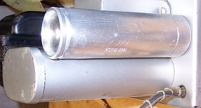
Filter Capacitors
Before servicing the filter capacitors, careful notes were made
of their positive terminal lug orientation, confirmed on the under chassis
photo. This is important since this radio uses a laced wiring harness, and
many leads from this harness connect to the filter capacitor lugs. The
three filter capacitors were normal aluminum screw based wet type capacitors
rated at 8mfd/500 volts DC. One (the final or output filter) was mounted out in the open, its case
grounded to the chassis. Two others were mounted inside a metal cover
which was lined with fish paper. These capacitors were insulated from the
chassis, and sat at more than 100 volts negative! The metal cover protected any
wandering fingers from this voltage. The visible capacitor (output
filter) was restuffed using an 8mfd/600 volt electrolytic obtained from Just
Radios in Canada. My process for restuffing these types of capacitors is as
follows:
- The capacitor was mounted in my small Unimat lathe and I deeply scored the
case about 1" above the base (almost through the case). I
finished the cut with a fine tooth hobby razor saw. In this case, there was
no liquid inside to be slung out as the capacitor was turned in the lathe -
it had already dried out.
- The center electrode foil was removed, but the aluminum center stud was
retained and cut short. A hole was drilled into the center stud and a
solder lug was attached using a 4-40 screw and nut.
- The plus lead of the replacement capacitor was attached to the solder lug.
- The negative lead of the replacement capacitor was extended using solid
bus wire and insulating spaghetti tubing through a drilled hole in the base
of the capacitor near the mounting threads..
- The two halves of the case were then reattached using 3/4" PVC
plumbing couplings and epoxy. If the cut is done cleanly, the cut is
hardly visible after reassembly. I normally add a few layers of
masking tape around the PVC coupling to take up any excess space.
- Once the epoxy has hardened, the negative lead was wrapped around the
screw base and the capacitor was re-mounted using its nut. The
negative lead was thus trapped between the capacitor base and the chassis,
providing the needed ground.
The two input filter capacitors are hidden under a metal cover
and are not visible. The capacitors were restuffed in a manner similar to the
output filter, again using 8mfd/600 volt electrolytics::
- The capacitor was mounted in my small Unimat lathe and I deeply scored the
case about 1" above the base (almost through the case). I
finished the cut with a fine tooth hobby razor saw. In this case, there was
no liquid inside to be slung out as the capacitor was turned in the lathe -
it had dried out.
- The center electrode foil was removed, but the aluminum center stud was
retained and cut short. A hole was drilled into the center stud and a
solder lug was attached using a 4-40 brass screw and nut.
- The plus lead of the replacement capacitor was attached to the solder lug.
- The top of the case was NOT reattached to the base. The negative
lead of both filters were left unconnected, and the capacitors mounted to
the chassis using the original fiber shoulder washers, fiber insulators,
ground lugs, and large nuts.
- A large piece of shrink tubing was used to insulate the positive leads and
studs of both filter capacitors.
- A small hole was drilled into the chassis between the two filters. A
piece of bare buss wire insulated with small spaghetti tubing was routed
through the hole and the buss wire connected to the two original capacitor ground
terminals, which had been soldered together.
- The top of the common ground buss was then connected to the negative
terminals of both 8mfd replacement capacitors.
- The fish paper insulator was then fit around both capacitors and the metal
cover reattached.
Block Capacitor and Other Metal Clad Capacitors
The line bypass capacitor consisted of three 0.01mfd
capacitors. It was cleaned out and three
0.01mfd/630 volt film capacitors installed as indicated in the schematic.
The tar was not replaced, since the back of the capacitor is not visible.
Another small can type capacitor contained a single 0.05mfd capacitor. This
capacitor couples the cold end of the second IF transformer to the volume
control through a 400K resistor. Originally it was sealed with tar and riveted to the
side of the chassis. After drilling out the rivets, disconnecting all
connecting wires and components, and removing the capacitor, the tar and
contents were removed and a 0.047mfd/630 volt capacitor installed. The tar
was not replaced. The capacitor was reattached using 6-32 screws and nuts.
The block capacitor containing seven capacitors was removed from
the radio. The nuts that hold the capacitor also secure the resistor
board. Several connections were temporarily disconnected from the resistor board
and it was moved back to allow access underneath, and for replacement of any out
of tolerance resistors. After removing the block capacitor, each lead was
identified and its length measured in order to maintain the original lead dress.
The cardboard cover was removed by bending back the retaining
tabs. I first tried using a heat gun to free up the contents. That did not
work. So I resorted to mechanical means to remove as much tar as possible.
Once down to the level of the capacitors, I was able to free up one capacitor
roll and remove it. Once it was removed, the remaining capacitors could be
removed. There was a common ground buss soldered to the can, which was
disconnected. The case was then cleaned up by removing as much tar as
possible mechanically (small screwdrivers) then soaking overnight in mineral
spirits. Final cleanup was done with lacquer thinner. New wire leads were
attached to the seven replacement capacitors, wired per the schematic. The
replacement capacitor assembly was wrapped in strips of paper towel to secure
and center it in the can. The sides of the can were insulated with fish paper to
prevent shorts. The can was then filled with melted rosin to hold everything in
place. The cardboard cover was reinstalled. Here are the restuffed block
and metal cased capacitors:

AVC Filter Capacitor
One small can type capacitor had been removed and replaced by
two tubular paper capacitors. The original had been attached to the
antenna and detector coil shields with rivets, and had been roughly removed -
damaging the coil shields. I had no clue what the original capacitor
looked like. Originally it contained two 0.1mfd capacitors, which were the
first and second AVC line filter/bypass capacitors (from the cold end of the
antenna and first detector coils to chassis ground). In a photo of another
unrestored chassis provided by an ARF member, this same capacitor had been
removed. But in his example, the original wire leads were still in
place. They were routed through holes in the tops of both coil shields,
near where the original can type capacitor would have been mounted.
Tubular capacitors were connected to the wire stubs in his chassis. This
helped me determine how the connecting leads were routed originally.
I have a collection of used metal can type capacitors. I did not
have an original dual 0.1mfd metal can type capacitor with two lugs.
However I did have a metal can type Micamold capacitor which was a dual
0.05mfd/600 volt oil filled capacitor with three lugs. Its mounting tabs
matched the mounting centers of the missing capacitor exactly! So I opened
up this capacitor (the back cover was soldered on) and removed its
contents. I also removed the center connection lug, since I only needed
two lugs. I mounted two 0.1mfd
630 volt film capacitors inside, each grounded to the metal case.
In order to mount this capacitor on the antenna and first
detector coil shields, I had to remove both coils from the radio - a difficult
and dangerous task, since all connecting wires and components must be removed
from the coil lugs. Once the coils were removed, I attempted to straighten
the shields as much as possible (they were riveted together and also riveted to
the chassis). The replacement small can capacitor was then attached to the shields using 6-32 pan head
screws from the inside of the shields, with star washers and 6-32 nuts on the
outside. Before tightening the screws, the connecting leads were attached to the
capacitor and routed through holes in the top of the shields. The leads were
left long so that they could be attached to the correct coil lugs once the coils were
reinstalled in the shields.

Metal Clad Power Resistor (Candohm)
Two sections of the four-section Candohm (metal clad) resistor were open.
The 14.7K open section previously had been jumped with a 10K 1 watt dogbone
resistor. The following 17.5K section was now also open. The two low
resistance sections (26 and 46 ohms) were OK. I hesitated to simply jump
the two open sections with appropriate wire wound resistors. The open sections
could at some point reconnect, or even worse, short to the chassis. The
14.7 and 17.5K sections form the screen grid divider, and thus are exposed to
full B+. I decided to fabricate a suitable replacement having the same
terminal spacing as the original resistor. This is important since the
wiring in this set is mostly in the form of a laced cable, and thus the leads to
the resistor have definite positions.
A piece of insulating material was used for the base (IIRC, salvaged from a
scrapped Tektronics Scope!). Flat head screws were countersunk in the
reverse side, and solder lugs attached to the top with nuts. Appropriate
wire wound resistors were then attached to the solder lugs. The resistor
base was sized so that the original mounting holes and screws could be used, and
the spacing between solder lugs was made close to the original so that the
original set's wiring would reach. I piece of insulating material (fish
paper) was placed under the base to prevent shorts to the chassis.
The values of the four sections of the resistor were documented on the
schematic, but not the power ratings! And also, no voltages are documented.
Using a tube manual, I used a B+ value of 250 volts and RF screen voltage of 100
volts (type 78 tubes). I used -15 volts for the 42 output tube bias. This
voltage drop through the 47 and 27 ohm sections of the candohm plus the
documented field coil resistance allowed calculation of the power dissipation in
the 47 and 27 ohm resistors. I replaced them with a 47
ohm 2 watt and 27 ohm 3 watt wire wound resistor. In order to calculate
the power dissipation in the 14.7K (I used 15K) and 17.5K screen divider sections of the
candohm, I used the tube manual screen current value listed as 1.7ma each (for the
three 78 tubes). This allowed calculation of the required power dissipation of
the two resistors: 1.63 watts for the 15K resistor and 1.37 watts for the 17.5K
resistor. I used 15K 6.5 watts
and 17.5K 5 watts. When later tested, the screen voltage was quite
close to the estimated 100 volts. Solving for these power dissipations
required use of two equations and two unknowns - High School Algebra? At 115
volts input, B+ was 235 volts (est. 250), B+ Screens was 97.6 volts (est. 100),
42 tube bias was -15.56 volts (est. 15), and B- was 103.8 volts (est. -100). After
about 1/2 hour of operation, the power resistors were barely warm.
Here is the replacement Candohm:

Small Resistors
Nine small resistors were out of tolerance by more than 20%
(some as high as 50%). All were 1/4 watt dogbone resistors. One
original dogbone resistor previously had been replaced by a modern type (the oscillator
tube grid resistor). Two of these dogbone resistors were in spaghetti
tubing and thus not visible. In these cases, I normally replace them
with standard carbon resistors. I collect NOS as well as used dogbone
resistors just for this purpose, and buy all I can find on eBay and at swap
meets. I did not have replacements available that were in tolerance.
In these cases I attempted to find a replacement that was the correct size and
had the correct measured value (within 20% tolerance) but not the correct
markings! I then repaint the resistor with the value required using hobby
enamel paint. In the two cases where the original resistors were hidden
inside spaghetti tubing, I used standard 1 watt carbon resistors (both
were 250K). In the photo below are some repainted resistors:

Tubes
All of the original tubes were re-used, since they were good or
only slightly weak.
Other Repairs
The original cloth covered line cord was worn and frayed and not
usable. However, a long piece of vintage cloth covered AC cord had been
used as an antenna, and connected to a short piece of shielded wire. This
wire was cut in half and used to replace the original cord. It also served
as a replacement for a future radio, since it was about 15' long. An old style brown bakelite plug was
attached.
The tone capacitor was original, but one end was connected to two leads
extending from the laced cable. One lead went to the plate of the 42 output
tube, and the other to the speaker cable (to the output transformer). But
the tone capacitor was found just hanging in space, and right above the power
transformer terminals (see Chassis Before
Restoration photo). It was hard to believe that with the high build
quality of this set that Grunow would have done this. Photos of another
chassis provided by an ARF member were similar. One hint was that in my
set, there remained part of a terminal lug on the tone capacitor lead. So the
capacitor must have originally been attached to some other part nearby.
There are no holes in the chassis nearby, or evidence of where a part was
attached to the chassis. My
guess is that the tone capacitor as well as the connecting leads were originally
connected to a lug on the AVC block capacitor, which had been removed in both my
set and the other reference chassis. I mounted a terminal strip on one screw of the
power transformer and used this as a junction point. This way the tone
capacitor would not be flopping around and risk the junction contacting one of
the power transformer terminals.
The lacing on the speaker cable was removed down to the break, then tied to
new lacing cord. The cable was then re-laced from the break all the way to
the speaker terminal attachment point.
Cabinet
The cabinet was vacuumed then cleaned using GoJo (white) hand cleaner and 00
steel wool. Nothing else was done to it.
Testing and Alignment
Once the radio had been reassembled,
the radio was powered up slowly using a fused Variac. This allows the
filter capacitors to reform. A DVM monitored the B+ voltage. The
radio came alive and worked well on both bands. But I did note that there was an
intermittent drop in volume. During alignment, the radio would oscillate and/or
motorboat if the antenna and first detector trimmers were adjusted for maximum
output. The oscillation and motorboating would go away if certain parts
were moved, and especially the antenna and first detector coil shields. These
shields (aluminum) were riveted to the steel chassis in several places.
But when I measured the resistance from the shields to the chassis I measure
between 8 and 15 ohms - and it varied with the positioning of the shields. Since
the cold end of both the antenna and first detector coil were grounded to the
chassis through the small block capacitor I added to replace the missing
capacitor, and since this capacitor was grounded through the coil shields, this
would certainly explain the oscillation and motorboating. I soldered a piece of
buss wire to the AVC capacitor can and connected the other end to an existing ground
lug (where the antenna shielded cable was grounded). This seemed to work, and the oscillation went away. The
radio was then aligned per the instructions in Riders.
Unfortunately, I do not think this is the end of any intermittent problems.
There are many aluminum parts such as tube shield bases attached to the chassis
with rivets. I suspect there are potential bad connections. But for
now the performance is excellent, with excellent sensitivity on both bands and
great tone quality due to its large speaker and solid cabinet.
Restoration Results
|
|
 |
Chassis After Restoration
|
 |


