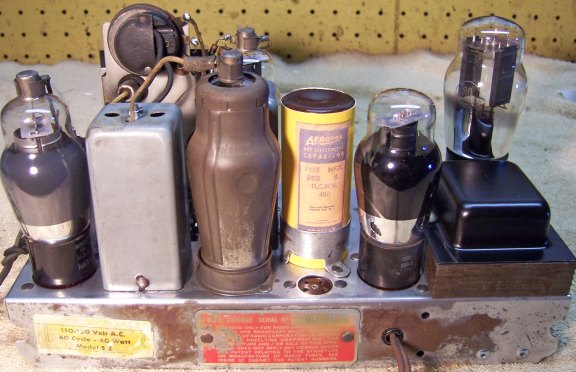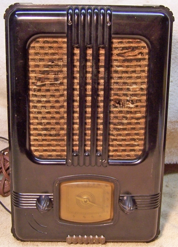
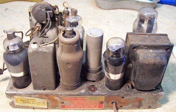
The only identifying markings found on this radio were the manufacturer R. P. C. CHICAGO, chassis type 5Z, and a serial number. There was no indication of a brand or model number. R. P. C. was Radio Products Corporation, located in Chicago, and one of the independents of the time. They sold radios to retailers under numerous private brands. They later merged with Continental Radio and Television, and finally changed the company name to Admiral. My example is very similar in appearance to a Mantola model 5A7 seen at Radio Attic Archives, but in ebony and has no Mantola or any other logo on the dial or elsewhere. Other radios using this same chassis and having similar style and sized cabinets are Admiral (Continental) DU-ETTE models 155-5Z, 155-5Z, 985-5Z, and 990-5Z for the 1938 model year. It is a 5-tube AC Superhet circuit radio with AVC. It receives only the broadcast band. The only source that I have found for a schematic for any of the above radios is at http://www.radiomuseum.org/r/continent1_985_5z.html. Any part number references will be relative to that schematic. The Radiomuseum model listing for the Admirals with the 5Z chassis also includes an advertisement which indicates that the radio can be used either horizontally or vertically (hence, DU-ETTE).
This example had seen major servicing in the past. I decided to attempt to reverse as many service modifications as possible, electrically restore it, and get it working.
My antique radio restoration logs
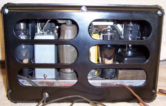
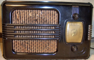
This radio was purchased on eBay. The cabinet was ebony bakelite with a bakelite back cover. There were no cracks or breaks. The radio is a very compact design, and especially for a radio with a power transformer and electrodynamic speaker The radio was sold as not working. The knobs, grille cloth, antenna and ground leads were original. The line cord and plug had been replaced. I try to avoid knowingly purchasing a radio that has been restored, as many collectors take shortcuts such as removing the original capacitors and filters. Unfortunately, subsequent examination showed that the radio had undergone extensive servicing, but no recent restoration. The chassis was dirty as found, but had minimal corrosion.
The radio has a standard 5-tube AC superhet circuit with AVC using all standard based tubes (6A7, 6D6, 75, 41, 80). Most radios of 1938 vintage would have used more modern octal tubes. An antenna wire (and ground) are needed.
The radio had been serviced several times, but not recently based on the vintage of components used..
The line cord and plug had been replaced.
The antenna and ground leads were original and largely intact.
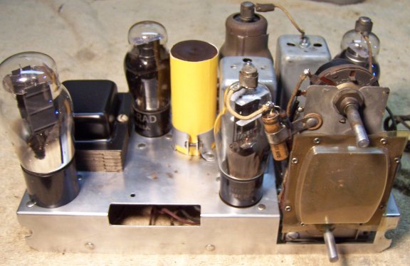
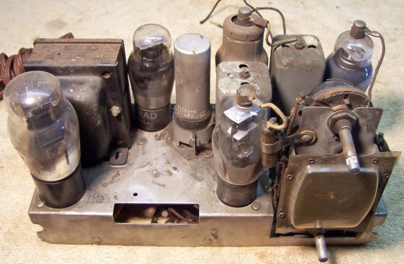
The power transformer had been replaced. The original was horizontally mounted. The replacement was a vertical mount, and was much larger than needed. There was hardly room for the 41 output tube which was adjacent to the transformer, and could not stand totally upright!
The tubes were varying brands and were likely not all original.
The filter capacitor had been replaced. The original appeared to have been a vertical clamp mounted unit, likely with wire leads, dual 5mfd, voltage unknown. The replacement was a smaller twist lock capacitor (30mfd/450 volts) mounted in the original clamp and insulated with electrical tape, plus an 8mfd/450 volt tubular capacitor installed under the chassis. The original capacitor was unusual in that the common for the dual unit was positive rather than negative, so a single standard dual twist lock capacitor could not be used.
A line bypass capacitor had been added, likely to avoid having to have a ground connection. No such capacitor is shown in the available schematic. Only two wax/paper capacitors were original (both Sprague branded), and three had been replaced (the usual suspects: AVC filter C4, audio coupling C2 and output transformer shunt capacitor C5).
All resistors were original - none had been changed.
My usual restoration procedure is to first make a complete survey of the condition of all components. The survey results guide my restoration strategy. If major and unique components are defective or missing and cannot be restored or replaced, I may elect to sell the radio for parts rather than restore it. I rarely apply power to a radio before restoration, even through a "dim bulb tester" or variac "to see if it works" (unless verifying an eBay seller's claim that the radio works). I always assume that all paper and electrolytic capacitors are leaky and thus should be replaced (I always "restuff" the original containers if possible). Any mica capacitors are assumed OK until testing proves otherwise.
Before starting repairs I made BEFORE photos of the chassis bottom. I use these photos to ensure that replacement parts and wiring are placed as close as possible to their original positions. Some radios are subject to problems such as oscillation or motor boating if wiring is re-routed or lead dress is not the same as the original. Plus one of my restoration objectives is that any repairs should be invisible.
I could not live with the existing power transformer if there was an alternative. I found a transformer in my junk box from an Airline model 62-352 radio, which was also a 5 tube radio from 1938, and which used the octal equivalents of the very same tubes used in the 5Z chassis. It was a small horizontally mounted type, with high voltage, 5 volt and 6.3 volt windings. It fit the existing mounting holes in the chassis exactly once the transformer's bottom shell was removed. This transformer was used to replace the existing transformer. Its top cover was rusty and paint was flaking off, so it was wire-brushed and repainted using semi-glass black enamel.
The broken terminal strip was replaced with a similar type with the same mounting spacing. The original was riveted to the chassis. The replacement was attached using steel pop rivets.
The three-section Candohm wire-wound resistor was intact, but one section (33 ohms) was out of tolerance. My standard fix was applied: squeezing the metal case over each terminal with a small C-clamp! As these resistor age, and due to heat, the insulation material likely contracts, which allows the terminals to lose their grip on the resistance wire element. After this squeezing process, all sections were within tolerance, and most were EXACT! This process can only be used where the fish paper insulation is in good shape. In this case, the resistor is a bias divider, and is NOT exposed to high voltages.
All out of tolerance (more than +/- 20%) resistors were replaced using similar type 1/2 watt carbon composition resistors. The replacements were either 5% or 10% tolerance, vs. the 20% tolerance originals (which are no longer available). 20% tolerance resistors would have been cheaper at the time of manufacture, and 20% tolerance is adequate for use in old radios.
As found, the radio had a mixture of capacitor brands installed, including two Solar wax molded types. The two original capacitors were branded Sprague. So I found dud Sprague branded capacitors in my dud capacitor stock that had the schematic-specified values. These were restuffed with new 630 volt film capacitors in an attempt to "reverse" prior servicing. I maintain a collection of branded (Zenith, Philco, GE/RCA) as well as generic (Sprague, Cornell-Dubilier, etc.) capacitors just for this situation.
The original filter capacitor was likely a cardboard cased tubular capacitor with wire leads. The diameter had to be about 1 3/16" in order to work in the clamp. My strategy was to find a suitable cardboard tube in my dud capacitor stock and restuff it. According to the schematic, the original was a dual 5mfd unit, voltage unknown. Either this capacitor would have had a common positive lead, or else both positive and negative leads for each section. The only dud I had in stock was slightly undersize and not secure in the clamp. The dud was restuffed using two 10mfd/450 volt capacitors with a common positive lead and separate negative leads. The case was then wrapped in several layers of printer paper until the capacitor was secure in the clamp. The paper was glued to the cardboard tube. An old cardboard capacitor case was scanned and its logo printed on the paper, which was tinted a similar color. The ends of the capacitor were sealed using rosin salvaged from servicing RCA Radiola Superhet catacombs.
The replacement line cord and plug were relatively recent and safe to reuse. The original was likely the same type, as cloth covered cords would not be likely in 1937.
All tubes tested good. They were a mixture of different brands, and likely not original. Brands included RCA, National Union and Tung-Sol. All were reused.
The speaker grille cloth and cardboard backing were first removed, then the cabinet and back cover were washed using dish detergent and toothbrushes to remove dirt from crevices. This left a dull finish on the cabinet. I first attempted using Brasso to polish the cabinet. Some improvement resulted. I also tried using a buffer wheel, and also Glazit polish. None of these worked very well. I finally used Johnson's wax, which provided an acceptable finish on the cabinet.
Once the radio chassis was reassembled and the tubes and tube shield installed, power was brought up slowly using a variac and isolation transformer. The radio came alive and worked immediately. The radio was then aligned. There are only six adjustments: the four trimmers on the IF transformers and the gang capacitor trimmers. There were no surprises. The IFs were set a 456kHz per the schematic (they were close as found). It was not possible to set the dial pointer correctly. The shaft to which the pointer is attached has hard stops on each direction of travel. The pointer is attached to the shaft with a screw. Unfortunately the screw cannot be accessed since it is behind the dial cover, which is attached with rivets! The cover would have to be removed to make the adjustment. The dial and dial cover are very fragile, and removal of the rivets would likely result in breakage. The pointer could not be made to track correctly using the trimmer adjustments.
The volume control seemed to work OK, even though it measured 2.7megs vs. a specification on 1 meg (it was original). There was no scratchiness and control was smooth, although there was still some sound heard at minimum volume. The radio was fairly sensitive and picked up all the usual local stations using a 6-foot wire antenna. A longer antenna only picked up more noise! My home and basement shop and very electrically noisy! Connecting the ground lead to a grounded electrical outlet made no difference.
Most objectives were met. I was able to restore the chassis to a pre-serviced condition, although I had no way of knowing what the original power transformer looked like. Also, the use of all Sprague branded capacitors was only a guess. The reproduction filter capacitor was the correct diameter, type, and approximate height. But its brand, color, and terminal lead characteristics were only a guess. Replacement resistors were 5% and 10% tolerance vs. the original 20% parts. In one case I was forced to use a 180K 1/2 watt resistor to replace the original 200K (although the replacement did measure 200K). 200K is no longer a standard value (values jump from 180K to 220K).
 |
 |