My antique radio restoration logs
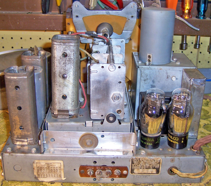
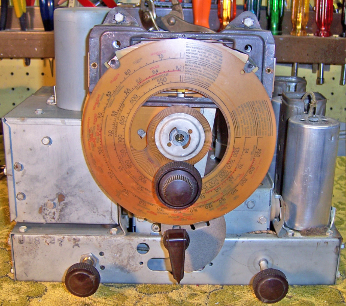
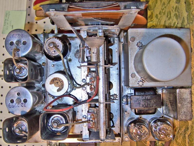
The Philco 37-624 is a 6 tube superheterodyne circuit radio with three bands. It operates on 6 volts DC only, and was used in rural areas before electrification. It features a tuned RF amplifier stage and push-pull class B output. The build quality of this set is very high. The band switching is quite complex, with unused coils shorted out. This set uses the Philco RF subchassis construction, which is quite difficult if not impossible to rebuild in place.
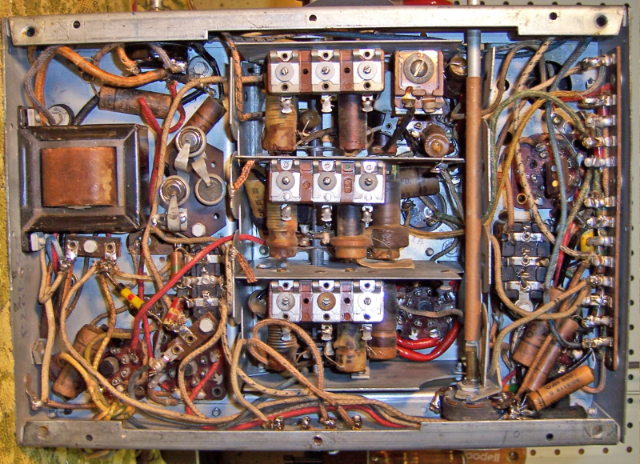
The radio appeared to be completely original as found. Since all the original components were still in place, I decided to try and retain the original top and bottom chassis appearance if possible.
My usual restoration procedure is to first make a complete survey of the condition of all components. The survey results guide my restoration strategy. If major and unique components are defective and cannot be restored, I may elect to sell the radio rather than restore it. I assume that all paper, bakelite block and electrolytic capacitors are leaky and thus should be replaced (I always "restuff" the original containers if possible).
The large outside tuning knob was broken in shipment due to very bad packing. The knob spring was lost. The parts were glued together with super glue and the knob spring was replaced.
The vibrator and vibrator transformer were OK. The power supply was removed from the radio for testing. The vibrator started up immediately. I replaced buffer capacitor with a new orange drop 1600 volt unit (hidden inside the power supply). New rubber grommets were used to remount the power supply on the chassis base.
The driver and output transformers were both OK.
IF transformers OK
All tubes were OK
All tube shields were present.
The tuning capacitor and vernier drive mechanism were very stiff
The 3 bias cells were assumed bad
The RF subchassis was removed from the chassis for repairs. All wiring going to the subchassis was tagged and then disconnected. Detailed information was logged as to where each wire went.
I then loosened one side of the 3-piece chassis to permit removal of the RF subchassis.
The tuning capacitor and vernier drive assembly was removed.
The bandswitch shaft was removed - pulled out from the front. Each switch wafer is keyed so that the shaft can only be inserted one way. However, I find it useful to place the switch in the broadcast band position and mark the position of each wafer (a couple of scratches with an Exacto knife). The wafers are returned to this marked position before the partitions are reinstalled.
I then removed all three RF subchassis partitions with their bandswitch wafer and coils attached (I logged, tagged and unsoldered leads that were attached to the chassis base or between sections)
At this point all the coils were tested and found to be OK
All resistors on the partitions were found to be OK
All paper-wax capacitors were removed and restuffed with modern components and resealed. Some capacitors are located between switch sections, and cannot easily be removed without first disassembling the RF subchassis.
The switch decks were cleaned with lacquer thinner and a tooth brush. Big Bath was then sprayed on the contacts and the rotors were turned using the bandswitch shaft after marking initial position.
The tuning capacitor was very stiff and difficult to rotate. I cleaned out the old caked grease in main bearing with lacquer thinner and replaced it with new grease.
The dial drive vernier was very stiff, and would not turn the tuning capacitor through its range. The reduction drive assembly was removed from the tuning cap, disassembled, cleaned, greased, and reassembled. The anti-backlash gears (there are two) were frozen. I added a generous amount of turbine oil and eventually got them freed up. Both were pre-loaded upon reassembly to minimize backlash.
I rebuilt C34, which is mounted on the RF Subchassis (marked NON-POLARIZED) in its original can (The original was 2uf+8uf at 200 volts). I rebuilt it using 4+10uf at 450 volts. The original can was cut about 1.25" up from base using my Unimat lathe, the contents removed, new caps inserted, then the two halves of the can were rejoined using PVC plumbing couplings cut in half plus epoxy cement. The common capacitor ground lead was routed through the base and clamped to the chassis under the mounting clamp. The original was likely NON-POLARIZED because the power supply would delivery the B+ at opposite polarity if the 6 volt input leads were connected to the wrong battery terminals. This would damage the capacitor.
The RF subchassis was then reassembled.
The three shock mounting rubber bushings were replaced with new reproductions
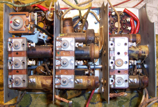
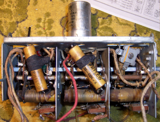
There were several wire wound resistors on the RF Subchassis. They are seen in RED Spaghetti tubing in the photos below. They are part of the filament and pilot lamp circuits. One was open. See the discussion regarding the pilot lamp - next topic below.
Photos of rebuilt RF Subchassis are below
 |
 |
The pilot lamp was a 2.1 volt, 120ma bayonet type and is no longer available. The original was defective. There is no current equivalent. It was suggested on the Philco Phorums to convert to a 6 volt (#47) bulb and rewire the lamp power supply to a 6 volt source. This was done. The power lead to the lamp socket originates in the RF subchassis, to one pin of the 1D5 used as a tie point. 6 volts is available from the adjacent pin, so the power lead was moved. This change really does not change the under-chassis appearance. The problem is that the pilot lamp, paralleled by a 16.6 ohm resistor, completes the filament circuit for the 1C7 and 1J6 tubes. The combination needs to drop 2 volts at 240ma. So if the lamp is removed, then the resistor needs to be 8.33 ohms. The existing 16.6 ohm resistor (flexible type) was open. It lives inside red spaghetti tubing on the RF Subchassis base - 1D5 socket. The original tubing can just accommodate a 1/2 watt carbon resistor, but was about 2" long. The power dissipation needs to be 0.48 watts. So I decided to use three 2.7 ohm 1/2 watt resistors, hand picked from my parts bin to total 8.3 ohms. Since three resistors are used, each only needs to dissipate 0.16 watts. I tested the three resistors inside the tubing and applied 2 volts for one hour. They only got slightly warm, and the resistance did not change. So it looks like this is the way I will go. One alternative was that there is a guy in the UK who makes reproduction flexible resistors. But since the resistor would be hidden inside spaghetti tubing, I decided not to go that way.
The power switch was mounted on the back of the tone switch. The tone switch was OK, but the power switch was stuck in the ON position. No amount of contact cleaner sprayed inside would free it. I also tried soaking the switch in lacquer thinner for some time. That also did not work. I was afraid that the contacts were welded together. I did have a replacement power switch (IRC type 42) in stock, but the original was riveted onto studs of the tone switch, and reassembly would have required drilling and tapping the studs to accept small screws to hold the replacement switch. As a last resort, with a replacement switch in hand, I added some turbine oil! That freed up the switch - it then worked. I did soak it again in lacquer thinner to remove the oil. It continued to work afterward.
The radio used 3 bias cells, totaling 3 volts, which provide bias voltage to the audio driver stage. Two of the cells were rebuilt using LR44 button cells, which equals 3 volts. The third original cell was left in place but bypassed under the cell holder. The cells were rebuilt by removing their contents, cleaning the case, and inserting a LR44 button cell, with the negative terminal up. The positive outside edge and back of the LR44 contacts the original case. The spring clip contacts only the negative center contact. This means that the polarity of the assembly must be reversed. This was accomplished by drilling out the rivet holding the original ground lug and first spring contact, removing the original ground lug (which contacts the metal spacer holding the assembly), and inserting a new ground lug on top of the assembly. This then becomes the new negative lead. The original ground lug was reused and wired to a rivet on the base of the second battery holder, thus providing a new positive lead, which connects to the chassis by way of the original metal mounting spacer.
The two flexible resistors (parts 43 and 44) which form a voltage divider across the filament of the 1F7 detector-first audio were intermittent and high in value. They were removed, and it was discovered that if the leads were recrimped they were OK. So they were re-installed. It is likely that corrosion had developed between the metal ends of the resistor and the lead wires.
The main power supply filter capacitor (part 64) is a metal cased unit mounted on the chassis. It was originally 4+8uf. It was restuffed using 4 and 10uf 450 volt capacitors.
All Philco bakelite block capacitors were removed, their contents removed, the cases cleaned with lacquer thinner, and new components installed inside. All wax-paper tubular capacitors were removed and restuffed with modern capacitors (630 volt in all cases). The ends were then resealed using discarded RCA catacomb wax (a combination of rosin and beeswax, I think!)
The chassis was cleaned with GoJo and steel wool. All parts were then reinstalled. Any defective or frayed wiring was replaced. The tubes and tube shields were cleaned and reinstalled. An antenna were connected and the radio attached to my 6 volt power supply. The B+ voltage was monitored. The radio worked the first time! The set was then carefully aligned.
Below are photos of the chassis before and after restoration. Before:

After Restoration (below):
