Philco 118B Cathedral Restoration
 |
The Philco118B is a large 8-tube cathedral style radio. It receives the
broadcast band and one short wave band. The radio had seen minimal servicing in the past and most original
parts were still in place. This being the case, I
decided to try to retain the original top and bottom chassis appearance if
possible. The radio was purchased on eBay.
The schematic and a partial parts list for the radio can be found on Nostalgia
Air. Any part number references in the text below reference that
schematic.
|
My
antique radio restoration logs
Previous Servicing
-
One capacitor of the capacitor bank 46 (marked BLUE) had been
disconnected and a tubular electrolytic capacitor tacked in its place.
-
One
resistor 45 had been removed and the connection to capacitor 46 removed. The
now unused section of capacitor 46 was paralleled with another section of
46. So it appeared there were multiple problems with capacitor 46!
-
All remaining filter, paper, and bakelite block capacitors
were original.
-
All remaining resistors were original.
-
Only two tubes were branded Philco and may have been
original (the two 78's). All others had been replaced.
Cleaning
After removal of the tuning capacitor, filter capacitors, and
bypass capacitor block, the chassis and remaining top components were cleaned using GoJo, steel wool, and
toothbrushes. The filter choke and audio driver transformer were
rusty. They were removed from the chassis, wire brushed, and repainted
with satin black enamel. The power transformer was not repainted.
Survey
These radios are difficult to service with limited access to
several parts. There are several errors in the available Riders schematic,
such as missing connections and incorrect part number references (such as 28).
My usual restoration procedure is to make a complete
survey of the condition of all components and repair all items before the radio
is tested. In this case, the eBay seller said the radio was powered up with
resulting hum and static. I did power up the radio through a watt meter and
fused variac to confirm this. The radio reacted as advertised, so
obviously there were no major component problems. I assume that all paper and electrolytic capacitors are leaky and thus should be
replaced (I always "restuff" the original components if possible). I
do not replace mica capacitors, but may test them in place if possible.
-
The power transformer was OK. The high voltage was balanced
on each side of the center tap with 10 volts applied to the primary through
a variac. It drew less than 10
watts at full line voltage (unloaded), and all filament voltages were correct.
I always make this test prior to restoration, since some transformers may
have shorted turns which may result in overheating after usage.
-
The speaker field coil, cone, and voice coil were OK.
-
All RF coils were OK (all were tested for resistance and/or
continuity).
-
The IF transformers were OK.
-
The filter choke was OK.
-
The audio driver transformer and output transformer were
both OK.
-
The original cloth covered power cord was OK.
-
The original speaker cable was OK.
-
All resistors were old style dogbone types. Some were
cast metal-end dogbones. All the cast-end dogbones were OK, but almost ALL
of the other resistors (13 total) were out of tolerance by more than 20%.
-
All supplied tubes tested good.
-
There was no conductivity between the center wiper contact
and the resistance element in the volume control. The end-to-end resistance
of the resistance element seemed OK. The switch was OK.
-
The shadow meter pilot lamp socket was broken and parts such
as the reflector were
missing.
-
The shadow meter was tested and was OK.
-
The dial string was heavily worn and the drive mechanism was
slipping.
-
The tuning capacitor grommets were OK. They were still
supple, but slightly shrunk allowing some movement of the capacitor.
-
One tube shield was missing
Restoration Strategy
Since almost all of the original parts were still in place, and
since this was going to be a "keeper", I decided to try to retain the
original top and bottom chassis appearance to the extent possible. All
original capacitors would be rebuilt in their original containers (restuffed),
including the distinctive Philco bakelite block capacitors, the original
filter capacitors, and the multi-unit bypass capacitor 46. Any out of tolerance
resistors would be replaced with the same types if available (otherwise
reproductions).
Repairs
Tuning Capacitor
The tuning capacitor was cleaned using my old Heathkit
ultrasonic cleaner and dilute ammonia. It would not all fit in the cleaner
at once, so several cleanings at different angles were needed. I normally remove the mica
trimmer insulators before cleaning in order to avoid damage. The capacitor was then cleaned using
soap, water, and toothbrushes. After drying with a heat gun, the bearings and grounding
fingers were lubricated using automotive distributor cam lubricant.
Dial Drive Cord and Associated Mechanism
The dial cord may have been original, but the outer cover was
missing in several places. There was considerable slippage between the
tuning knob shaft and the upper pulley. I posted questions about this
problem on both the Antique Radio
Forums and the Philco Phorum.
I did not get a definitive answer from either source. My thoughts were that the
upper fiber pulley, which is hinged on a link, was worn excessively and thus
could not be driven from the metal knob shaft. My fix was to install a
small vinyl grommet on the tuning knob shaft in the area where it contacts the
upper pulley. I then replaced the dial cord and strung
it up in the standard way. I used genuine Philco dial cord (45-xxxx)
which is a larger diameter and very flexible. The mechanism now worked
OK. However, it was obviously not clear how long this repair would
last. I plan on searching for a pulley that will fit on the dial knob
shaft and replace the hinged fiber pulley which is worn. The hinged pulley
would then be removed and the knob shaft and pulley would drive the cord
directly.
Volume Control
The volume control was removed from the radio and disassembled.
It was discovered that corrosion had developed between the floating brass wiper
contact and the metal contact. The brass part was cleaned in my ultrasonic
cleaner, and the mating part cleaned with lacquer thinner on a Q-tip.
Continuity was then re-established. The carbon element was cleaned and the
control seemed to work OK, although there was a rough place observed as the
control was rotated. I will have to await final assembly of the radio to
see if the control works OK or has to be replaced. Since it is a tapped
control, finding a suitable replacement would be difficult.
Resistors
The radio uses
"dogbone" type resistors. Several of of them were the older
"cast end" type with solid metal ends. The remainder were later
"wound end" types with the radial component leads wound around the resistance
element and then soldered together. Almost ALL of the wound-end dogbones had drifted out of
acceptable tolerance range, and would have to be replaced. In most cases,
I would replace an original resistor only if it was not within +/- 20% (or
marked tolerance). Any "dogbone"
resistors would be replaced with the same type resistor.
I keep a stock of NOS and used "dogbone" resistors, and buy all I can
on eBay and radio swap meets! Of course, most of these resistors, even NOS resistors,
would have also
drifted in value and no longer have their marked values. My solution is to
find a replacement resistor of the correct value and size as measured (ignoring the
markings), and then repaint it to the needed value codes using enamel hobby
paint!
I was able to find suitable resistors in my
stock of "dogbone" resistors for most replacements. But in a couple of
cases I was forced to use a 1 watt dogbone rather than the original 1/2 watt
types. Here are the replacement resistors. The 20K (top left) and metal
end 240K (bottom right) should be 1/2 watt wound-end dogbones. The 10K 1/2
watt resistor (bottom left) is NOS and in tolerance.

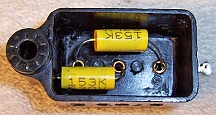
Capacitor Bank 46
The 4-unit bypass capacitor bank 46 was restuffed with new
capacitors. It originally contained capacitors of 2.0 and 1.0 mfd at
various voltages (300, 350, and 450 volts). I originally thought that this was a
paper type capacitor. But when it was opened up for restuffing it was
found to be an electrolytic capacitor. The insulation between foil sections was
moist rather than dry like a wax-paper type capacitor. So it was restuffed
using four 4.7mfd 450 volt radial type electrolytic capacitors. There was
plenty of room inside the case for these capacitors. The restuffing process for
this capacitor was as follows:
- The capacitor was mounted in my small Unimat lathe and deeply score the case about 1"
above the base (almost through the case). I finished the cut with a fine tooth hobby razor
saw.
- The original contents were removed from the case by pulling. There
was no cement or tar holding the contents inside the case.
- The foil connections to the base terminals were cut using a sharp Exacto
knife with #11 blade. The paper insulation or dielectric was also removed
from around the rivets retaining the terminal lugs.
- The inside of the case and the base were cleaned using soap, water, and a
toothbrush. They were then dried using a heat gun.
- Small holes were drilled into the base near each terminal lug. The holes
were drilled using a small numbered drill and a Dremel Moto-tool. The holes
were just large enough to clear a #22 solid bus wire.
- The positive leads of each of the four 4.7mfd replacement capacitors were
spliced to a piece of #22 bare bus wire, insulated with #11 spaghetti
tubing, passed through the holes in the base, and soldered to the terminal
lugs.
- The negative lead of the replacement capacitors were connected to a common
negative #22 bus wire. A small hole was drilled in the top of the capacitor
for this common negative lead. This lead was connected to the clamp screw which
holds the capacitor in place.
- The two halves of the case were then reattached using 3/4" PVC plumbing
couplings and epoxy. I normally add a few layers of masking tape
around the PVC coupling to take up any excess space.
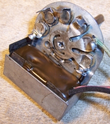
Filter Capacitors
The two original can
type filter capacitors 73 and 74 were rebuilt in their original cases
using new electrolytics. The wet 8mfd 450 volt unit 74 was restuffed using a 10mfd/450 volt electrolytic. The dual
dry unit 73 (8mfd 450 volt and 10mfd 50 volt) was restuffed with a
10mfd/450 volt and a 22mfd/50 volt electrolytic. My restuffing
process for the wet type capacitor 74 was as follows:
- The capacitor was mounted in my small Unimat lathe and the case deeply scored about 1"
above the base (almost through the case). I finished the cut with a fine tooth hobby razor
saw. In this case, there was no liquid inside to be slung out as the
capacitor was turned in the lathe.
- The center electrode foil was removed, but the aluminum center stud was
retained and cut short. A hole was drilled into the center stud and a solder lug
was attached
using a 4-40 brass screw and nut.
- The plus lead of the replacement capacitor was attached to the solder lug.
- The negative lead of the replacement capacitor was extended using solid bus
wire and insulating spaghetti tubing through a drilled hole in the base of
the capacitor near the location of the original negative grounding lug.
- The two halves of the case were then reattached using 3/4" PVC plumbing
couplings and epoxy. If the cut is done cleanly, the cut is hardly
visible after reassembly. I normally add a few layers of masking tape
around the PVC coupling to take up any excess space.
- Once the epoxy has hardened, the original grounding lug and cardboard
insulators were reinstalled. The negative lead of the replacement filter
capacitor were then attached to the grounding lug. The insulating sleeve
totally hides the repair.
The process for restuffing the dry type capacitor 73 is similar to the
above.
However all of the contents have to be removed. Holes are drilled into
the hard rubber base near existing terminals. The common ground
connection is also routed through the base near the location of the original
ground lug.
 |
|
Rebuilt Filter Capacitor Cans |
Paper Capacitors
All paper capacitors were rebuilt in their original cases
using modern 630 volt film capacitors in order to maintain the original
under-chassis appearance. The radio used two types: most were Philco
bakelite block type capacitors but a few were normal tubular types. For
the tubular types, I remove the capacitor from the radio by unsoldering its
leads. The lead lengths and any insulating sleeving lengths are then
noted. I take notes of which lead goes where in the radio, and identify
the capacitor using marking tags (which note the part identification and the
location in the notes where it was removed).
The tubular types are easy to restuff.
They have crimped ends retaining a fiber disc. My restuffing process for
these types is:
- Slice through the cover about 1/16" from one end using a new, sharp
single edge razor blade.
- Pull out the component lead and remove the fiber disc on that end.
- Heat the cover using a heat gun, which will allow removal of the contents
including the fiber disc and component lead on the opposite end.
- Heat the empty cardboard cover using a heat gun to melt any wax left on the
outside, and then wipe with a paper towel to remove the wax and dirt.
- Wrap the replacement axial film capacitor in a strip of paper towel cut to the width of the replacement
capacitor in order to center the component in the original case. I
used 0.047/630 volt capacitors. In one case, the original replacement
component lead length
was long enough and did not have to be extended. In another case, both
ends had to be extended using #20 bare bus wire (the splice was made close to
the capacitor body so that it was hidden inside the case). #20 bus
wire is closer to the original component lead diameter than that of the
replacement part used for the restuff.
- Insert the fiber disc and the replacement capacitor in the original case,
stopped by the case end that still has its crimped end.
- Melt a small amount of rosin to fill up most of the gap remaining on the
open end. I use rosin salvaged from servicing RCA Radiola Superhet
catacombs. Hot melt glue could also be used. While still molten, the
remaining fiber disc and the end of the case is reinstalled and a small
additional amount of rosin added to secure it.
|

|
|
Restuffed Tubular Capacitor
|
Bakelite Block Capacitors
All original Philco bakelite block capacitors were removed from the radio
(one at a time, making careful notes of connections), their contents
removed, cases cleaned using lacquer thinner, and restuffed using modern 630
volt film capacitors. Before removing the contents I unsolder the internal
capacitor leads from the outside terminals and clean off the terminals. I use
mechanical methods of removing the bulk of the potting tar and capacitors (small
screwdrivers). One must be careful NOT to pry against the bakelite case,
as it is easily broken. Some collectors use heat to remove the contents.
Here is the restuffed capacitor 69 (the line bypass capacitor, Philco part
number 3793), which contains two 0.015mfd capacitors:
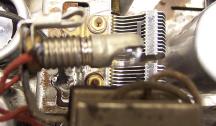
Tone Control Switch Repair
The tone control switch 52 contained three capacitors buried in tar. All
are 2000pf according to the schematic. The capacitors within the switch were replaced using 0.0022mfd 630 volt
capacitors (which all measured close to 2000pf on my HP973 meter). The
original insulator was retained. The contacts were cleaned with lacquer thinner
and an old tooth brush. The new capacitor leads were extended using #22 bare bus
wire insulated with thin spaghetti tubing. The tar was replaced using melted
rosin from servicing RCA Radiola Superhet catacombs. Here is a similar restored
switch from my Philco 16B:
Other Repairs
The pilot lamp socket for the shadow tuning unit was
rebuilt. The remnants of the original socket were first removed by
grinding off the end of the retaining rivet/center electrode and removing the
fiber insulators.
This left a protruding metal bracket. This bracket was ground down in
width on a
bench grinder so that a clip-on pilot lamp socket could be attached. The position of the lamp is critical and has
to be adjusted by bending its mounting bracket once the radio is reassembled and
tested - it affects the appearance of the shadow tuning meter face. I found
a replacement reflector in my junk box and installed it on the bulb and socket
(this prevents excess light from the rear of the cabinet). Here is the restored lamp:
Cabinet
The cabinet was in excellent shape, although all except the front panel was
somewhat oxidized (dark). It was cleaned with GoJo hand cleaner
and 00 steel wool, followed by a coat of Johnson's Paste Wax. The
grille cloth was slightly loose in places. I removed the cardboard backing from
the cabinet and gently lifted the affected areas of the cloth from the
backing. A very thin coating of carpenters wood glue (Titebond) was
applied to the backing. The cloth was locally stretched to eliminate sagging and
secured with spring clamps until the glue was dry. The result was a
completely flat grille cloth.
Pieces of one of the cabinet labels was found
loose inside the cabinet. There were two parts which formed most of one
side of the label. There was also a tightly wound roll that was the other
side of the label. All pieces were sprayed on both sides with a mist of water
and flattened as well as possible. The pieces were then placed on a piece
of notebook divider material and reassembled as good as possible. This was
very difficult since the pieces were very fragile, and also the glue was
reactivated by the water! The reassembled label was covered by a piece of
waxed paper and a piece of plywood and a heavy weight until dry. The
result was far from perfect, but it beats a total loss of the label. The
label was then reattached to the inside of the cabinet above the existing tube
layout label.

Testing
After the radio was completely reassembled, power was applied through a
wattmeter and fused Variac. Power was brought up slowly while monitoring
the B+ voltage and the wattmeter. The radio came alive and worked on both
bands - no assembly errors! The radio was then
aligned. The
shadow meter and its replacement lamp socket worked OK. The repaired
volume control worked perfectly.
Restoration Results
Most of my restoration objectives were met, but not all. There was no
intention of restoring the set to factory new appearance! My objective is
usually to reverse any prior servicing and make the radio appear to have never
been repaired. I do not go so far as to artificially "age"
solder joints, as do some collectors! Nothing gives away a restoration
faster than bright and shiny solder joints. Here are some of my
"misses":
- Several replacement dogbone resistors were not the same size as the
originals.
- The shadow meter lamp socket was not original.
Chassis Before Restoration

After Restoration Photos