Philco 16B Cathedral Restoration
 |
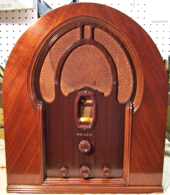
The Philco16B is a large 11-tube cathedral style radio. My example was
the Code 121 version with 5 bands. The radio had seen minimal servicing in the past and most original
parts were still in place. This being the case, I
decided to try to retain the original top and bottom chassis appearance if
possible. The radio was purchased on eBay and had been completely
disassembled for restoration by the owner. This made shipping much
safer, since individual components could be boxed separately. The
chassis had been shipped separately from the cabinet and the remainder of
the parts.
The schematic and a partial parts list for the radio can be found on Nostalgia
Air. Any part number references in the text below reference that
schematic. |
My
antique radio restoration logs
Previous Servicing
-
One capacitor (E) of the capacitor bank 62 had been
disconnected and a tubular electrolytic capacitor tacked in its place (the
original was a paper type bypass capacitor).
When that capacitor bank was removed for rebuilding, all the sections except
the one replaced measured very close to specification, and with minimal
leakage. The section that had been replaced was rated at 1.0mfd but measured only 0.57mfd.
-
All remaining filter, paper, and bakelite block capacitors
were original.
-
All resistors were original.
-
Only two tubes were branded Philco, so most had been
replaced at least once. A 77 tube had been replaced with a 6C6 (an
acceptable
substitute).
-
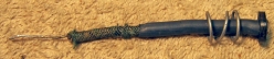
A piece of copper wire had been wrapped around the volume
control shaft under the retaining circlip, likely to increase the pressure of
the rotating wiper on the resistance element.
Cleaning
After removal of the tuning capacitor, filter capacitors, and
bypass capacitor block, the chassis and remaining top components were cleaned using GoJo, steel wool, and
toothbrushes.
Survey
These radios are difficult to service with limited access to
several parts. Also, there are many documented changes which must be
considered since the schematic, parts list, and parts placement diagram will
likely not match the radio as built.
My usual restoration procedure is to make a complete
survey of the condition of all components and repair all items before the radio
is tested. I assume that all paper and electrolytic capacitors are leaky and thus should be
replaced (I always "restuff" the original components if possible). I
do not replace mica capacitors, but may test them in place if possible.
-
The power transformer was OK. The high voltage was balanced
on each side of the center tap with 10 volts applied to the primary through
a variac. It drew less than 10
watts at full line voltage (unloaded), and all filament voltages were correct
-
The speaker field coil, cone, and voice coil were OK.
-
All RF coils were OK (tested for resistance and/or
continuity).
-
The IF transformers were OK.
-
The filter choke was OK.
-
The audio driver transformer and output transformer were
both OK.
-
The original power cord had been cut off - the original plug
was present in the box of parts provided.
-
The original speaker cable had a few areas with damaged
insulation, which was very brittle and would break if bent. The leads
to the QAVC quieting switch had the same problem where the leads exited the
chassis.
-
One original dogbone type resistor was out of tolerance.
Several others were over 20% high but were not in places where values are
critical, so they were left (at least until the completion of testing).
-
All the supplied tubes were good except for one of the type
77s.
-
The volume control and switch were defective.
-
The inter-station quieting adjustment potentiometer 82 was
open.
-
The inter-station quieting switch 54 originally was not working, but
responded to an injection of GC Big Bath cleaner and repeated operation.
-
The dial scale was warped, likely due to shrinkage of the
material. There was also a small piece missing on the outside
edge. The large rubber drive wheel was in good shape.
-
The dial drive mechanism was slipping in low speed mode and
could not be shifted to high speed mode due to hardening of the rubber tire
on one of the wheels.
-
The shadow meter pilot lamp socket had failed due to
deteriorated rubber parts, which will be the case in all Philcos that use
this type of socket.
-
The shadow meter coil showed normal conductivity and
responded well when tested using 1.5 and 9 volt batteries. Originally, the
permanent magnet on the back side was loose. It was reattached using a
couple of dabs of melted rosin salvaged from servicing RCA Radiola Superhet
catacombs (a reversible repair method!)
-
The ground connection (Fahnestock clip) was broken off -
only a fragment remained.
Restoration Strategy
Since almost all of the original parts were still in place, and
since this was going to be a "keeper", I decided to try to retain the
original top and bottom chassis appearance to the extent possible. All
original capacitors would be rebuilt in their original containers (restuffed),
including the distinctive Philco bakelite block capacitors, the original
filter capacitors, and the bypass capacitor block. Any out of tolerance
resistors would be replaced with the same types if available.
Repairs
Tuning Capacitor Mounting Grommets
The tuning capacitor mounting grommets were badly deteriorated
and stiff, allowing the capacitor to flop around. Unfortunately the exact
replacement parts needed were not available from Renovated
Radios. The closest available part was GLg-Tuner. While these
parts fit the chassis hole and the center hole is the correct diameter, they are
only 7/16" high (1/2"+ is needed since there is a 1/2" steel
spacer used in the center). These grommets were extended by gluing on some
GHal-S40 grommets that had been trimmed of their projections. This
additional 1/16"+ in height worked out well. The parts were
attached using super glue.
The tuning capacitor was cleaned using my old Heathkit
ultrasonic cleaner and dilute ammonia. It would not all fit in the cleaner
at once, so several cleanings at different angles were needed. I normally remove the mica
trimmer insulators before cleaning in order to avoid damage. But in this
case they were left in place, since the notes in Riders indicate that the
alignment of two of the tuning capacitor trimmers is factory adjusted and sealed
(there are no instructions provided for adjusting these trimmers in the field -
so I decided to leave them alone). The capacitor was then cleaned using
soap, water, and toothbrushes. After drying with a heat gun, the bearings and grounding
fingers were lubricated using automotive distributor cam lubricant.
QAVC Adjustment Potentiometer
The 10K wire wound QAVC inter-station quieting adjustment
potentiometer 82 (on the rear chassis) measured open and also intermittent in
operation. It was removed from the set and the rivet retaining the
rotating member and center terminal removed. This allowed the resistance
element to be removed for cleaning and inspection. Unfortunately, there
were many breaks in the resistance wire and the control could not be
repaired. It was replaced with a 10K ohm 5 watt linear taper wire wound
control having a screwdriver adjustment slot (the original had a short knurled
shaft). The replacement control was slightly smaller physically than the
original. The original also had a tap which was not used in the radio.
Volume Control and Switch
The volume control showed signs of previous trouble, in that a
piece of solid copper wire had been wound around the shaft between the retaining
circlip and the front bushing, and then soldered. I assumed that this was
an attempt to increase the pressure of the rotating element on the resistance
element. The control measured a very high resistance and was intermittent
in operation. This type of control cannot be cleaned - the resistance
element is nothing more than a thin film of carbon on a cardboard or fiber backer
board. A sheet of flexible stainless steel separates the wiper from the
resistance element. Any attempt to clean the element will simply remove the
thin carbon layer. The AC switch on the back of the control was also
defective. The control was rated at 2 megohms with a tone control
tap. It was replaced by an NOS IRC Q13-139X control with 76-1 switch. The
standard D-type shaft that comes with these controls does not fit snugly into
the Philco knob. So a piece of sheet brass was epoxied to the end of the shaft once it was trimmed to length.
Resistors
The radio uses
"dogbone" type resistors. About half of them were the older
"cast end" type with solid metal ends. The remainder were later
"wound end" types with the radial component leads wound around the resistance
element and then soldered. Only one original resistor had drifted out of
acceptable tolerance range, and would have to be replaced. In most cases,
I would replace an original resistor only if it was not within +/- 20% (or
marked tolerance). Any "dogbone"
resistors would be replaced with the same type resistor.
I keep a stock of NOS and used "dogbone" resistors, and buy all I can
on eBay and radio swap meets! Of course, most of these resistors, even NOS resistors, have also
drifted in value and no longer have their marked values. My solution is to
find a replacement resistor of the correct value and size as measured (ignoring the
markings), and then repaint it to the needed value codes using enamel hobby
paint! In the case of this radio, only one "dogbone" resistor had to be
replaced (a 10K 1 watt unit). I found a NOS 15K 1 watt dogbone resistor in
my stock that measured exactly 10K. Thus I only had to repaint the end
color black.

Capacitor Bank 62
The 5-unit bypass capacitor bank 62 was restuffed with new film
capacitors. It contained capacitors of 2.0, 2.0, 0.5, 0.5, and 1.0 mfd. 630 volt film
capacitors were used to restuff this capacitor (values used were 0.47, 1, and 2.25 mfd).
This capacitor is very easy to rebuild. Once the internal leads were
removed from the top terminals and the ground connection unsoldered from the
case, the
cover can be removed. I ground off the rivets on the cover, assuming they
were holding the cover. As it turns out, they were only holding the
terminal board - nothing was holding the top cover other than the leads to the
capacitor body inside. The capacitor pack can then be removed as a unit by
sliding a putty knife or thin blade between the fish paper insulation and the metal case. Very
little of the tar was stuck to the metal case.
Filter Capacitors
The two original can
type filter capacitors 87 and 88/75 were rebuilt in their original cases
using new electrolytics. The wet 8mfd 450 volt unit 87 was restuffed using a 10mfd/450 volt electrolytic. The dual
dry unit (8mfd 450 volt and 10mfd 50 volt) was restuffed with a
10mfd/450 volt and a 22mfd/50 volt electrolytic. My restuffing
process for the wet type capacitor 87 is as follows:
- The capacitor is mounted in my Unimat 3 lathe and scored about 1"
above the screw base. The capacitor is held in the 3-jaw chuck using
its mounting nut and by the live center on the opposite end. I finish the cut with a fine tooth hobby razor
saw - especially if the capacitor still has liquid electrolyte inside!
- The center electrode foil is removed, but the aluminum center stud is
retained and cut short. A solder lug is attached to the center stud
using a 4-40 brass screw and nut.
- The plus lead of the replacement capacitor is attached to the solder lug.
- The negative lead of the replacement capacitor is extended using solid bus
wire and insulating spaghetti tubing through a drilled hole in the base of
the capacitor near the location of the original negative grounding lug.
- The two halves of the case are then reattached using 3/4" PVC plumbing
couplings and epoxy. If the cut is done cleanly, the cut is hardly
visible after reassembly. I normally add a few layers of masking tape
around the PVC coupling to take up any excess space.
- Once the epoxy has hardened, the original grounding lug and cardboard
insulator are reinstalled. The negative lead of the replacement filter
capacitor is then attached to the grounding lug.
The process for restuffing the dry type capacitor 88/75 is similar to the
above.
However all of the contents have to be removed. Holes are drilled into
the hard rubber base near existing terminals. The common ground
connection is also routed through the base near the location of the original
ground lug.
 |
|
Rebuilt Filter Capacitor Cans |
Paper Capacitors
All paper capacitors were rebuilt in their original cases
using modern 630 volt film capacitors in order to maintain the original
under-chassis appearance. The radio used two types: most were Philco
bakelite block type capacitors but a few were normal tubular types (mentioned in
the CHANGES for Run 8 - 30-4020-X,
.05mfd). For
the tubular types, I remove the capacitor from the radio by unsoldering its
leads. The lead lengths and any insulating sleeving lengths are then
noted. I take notes of which lead goes where in the radio, and identify
the capacitor using marking tags (which note the part identification and the
location in the notes where it was removed).
The tubular types are easy to restuff.
They have crimped ends retaining a fiber disc. My restuffing process for
these types is:
- Slice through the cover about 1/16" from one end using a new, sharp
single edge razor blade.
- Pull out the component lead and remove the fiber disc on that end.
- Heat the cover using a heat gun, which will allow removal of the contents
including the fiber disc and component lead on the opposite end.
- Heat the empty cardboard cover using a heat gun to melt any wax left on the
outside, and then wipe with a paper towel to remove the wax and dirt.
- Wrap the replacement axial film capacitor in a strip of paper towel cut to the width of the replacement
capacitor in order to center the component in the original case. I
used 0.047/630 volt capacitors. In one case, the original lead length
was long enough and did not have to be extended. In another case, one
end had to be extended using #22 bare bus wire (the splice was made close to
the capacitor body so that it was hidden inside the case).
- Insert the fiber disc and the replacement capacitor in the original case,
stopped by the case end that still has its crimped end.
- Melt a small amount of rosin to fill up most of the gap remaining on the
open end. I use rosin salvaged from servicing RCA Radiola Superhet
catacombs. Hot melt glue could also be used. While still molten, the
remaining fiber disc and the end of the case is reinstalled and a small
additional amount of rosin added to secure it.
|

|
|
Restuffed Tubular Capacitor
|
Bakelite Block Capacitors
All original Philco bakelite block capacitors were removed from the radio
(one at a time, making careful notes of connections), their contents
removed, cases cleaned using lacquer thinner, and restuffed using modern 630
volt film capacitors. Before removing the contents I unsolder the internal
capacitor leads from the outside terminals and clean off the terminals. I use
mechanical methods of removing the bulk of the potting tar and capacitors (small
screwdrivers). One must be careful NOT to pry against the bakelite case,
as it is easily broken. Some collectors use heat to remove the contents.
Here is the restuffed capacitor 90 (the line bypass capacitor, Philco part
number 3793E), which contains two 0.015mfd capacitors:
One capacitor also contains a wire wound resistor, which was reused.
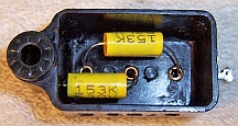
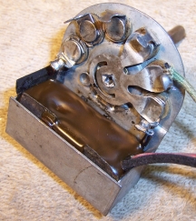
Tone Control Switch Repair
The tone control switch 79 contains two capacitors buried in tar. The
CHANGES listed in Riders indicate that the two capacitors are 0.003 and
0.09mfd. An associated external capacitor 80 contains two 0.025mfd
capacitors. Note that these values DO NOT correspond to the
schematic! The capacitors within the switch were replaced using
0.0033 and 0.1mfd 630 volt capacitors. The bakelite block capacitor 80 was
rebuilt (as shown above) using two 0.022mfd 630 volt capacitors. One of
the two lead wires (black) had to be replaced, since it was rubber insulated and
the insulation was falling apart. The red lead, although also rubber, was OK and was
reused. The tar was replaced using melted rosin salvaged from servicing RCA
Radiola Superhet catacombs. Before new parts were installed, the control was
cleaned in my old Heathkit ultrasonic cleaner using dilute ammonia. Here
is the restored control:
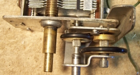
Tuning Mechanism Vernier Drive
The tuning shaft was slipping and would not rotate the tuning
capacitor. This was due to hardened and worn rubber tires on the two drive
wheels. The mechanism
was removed from the tuning capacitor and the failed rubber removed mechanically
(not easy). The
two rubber tires were replaced using modern O-rings as documented in an article
at Philcoradio.com.
The knurled shaft that engages the large rubber ring on the dial scale hub was
cleaned using an Exact knife in order to remove debris and rubber embedded in
the grooves. This results in a better grip on the rubber ring.
Dial Scale
The dial scale that came with the radio was hopelessly warped, likely due to
material shrinkage. I was able to acquire a replacement dial assembly with a fairly
straight dial scale. However, the large rubber drive wheel on this
replacement unit was in
poor condition with much material loss and wear. The rubber drive wheel on
the original dial scale was in good but not perfect condition. So I decided to remove
the dial scale from the replacement dial and install it on the original hub with
the better drive wheel. The dial scale originally was attached using brass rivets.
These were carefully ground off and replaced by 4-40 x 3/16" round head brass screws and
small nuts. The original holes in the metal hub had to be slightly enlarged to accommodate
the screws. After assembly, there remained one "dead spot" around
1400 on the dial. The remainder of the dial worked smoothly.
Power Cord
The power cord was replaced using brown rayon covered reproduction lamp code
from Antique Lamp
Company. The original AC plug was reused.
Other Repairs
The chassis mounting washers were replaced using CW-5 washers
from Renovated Radios.
The pilot lamp socket for the shadow tuning unit was
rebuilt. All the deteriorated rubber parts were first removed. The
spring and center contact were saved and re-used. I replaced the failed rubber
insulation with a 3/8" fiber washer with its diameter ground down to fit
loosely inside the
socket. I do this by attaching several fiber washers to a long 6-32 screw
and then grind their outside edges on a bench grinder until they can slide into
the Philco socket. This way I make several spares, since all Philco radios
seem to have this problem. The original power lead was also re-used and secured
behind the fiber washer using two
layers of 1/8" heat shrink tubing. The position of the lamp is critical and has
to be adjusted by bending its mounting bracket once the radio is reassembled and
tested - it affects the appearance of the shadow tuning meter face.

The broken/missing GROUND connection (a Fahnestock clip) was replaced using a
similar part I found in my junk box. The original was attached with a
rivet. I secured it using a 6-32 screw, which also retained a ground lug
on the back side. The 6C6 tube substitute was replaced with the original type 77 (although the
6C6 is a close substitute). A defective type 77 (Philco) was
replaced. Breaks in the speaker cable and wiring to the QAVC switch were
repaired using heat shrink tubing.
Cabinet
The cabinet was in excellent shape. It was cleaned with GoJo hand cleaner
and 00 steel wool, followed by a coat of Johnson's Paste Wax. The knobs
were cleaned with GoJo and then lightly polished on a bench grinder small
soft buffing wheel using plastic polishing compound.
Testing
After the radio was completely reassembled, power was applied through a
wattmeter and fused Variac. Power was brought up slowly while monitoring
the B+ voltage and the wattmeter. The radio came alive and worked - no assembly errors! The radio was then
aligned, which is a complex process and required careful reading (I went through
the procedure twice just in case). The
shadow meter worked OK after adjustments documented at The
Philco Repair Bench Service Hints and Tips. The QAVC inter-station quieting feature
worked, but was very difficult to adjust. Likely this was due to a large amount of
noise/buzz in my shop - there is really NO quiet place on the dial on band 1.
If the control was adjusted to eliminate all the noise, the weak stations were also
eliminated. This may be normal, since this radio was made before high levels of
AM interference from power lines, fluorescent lighting, wall wart power
supplies, and computers existed.
While the radio appears to be quite sensitive, the AVC voltage only varies
from about -0.5 volts (off station) to -5.5 volts (strongest local
station). However, we are located in a rural area and my antenna is only a
40' length of wire strung across the basement ceiling. This lack of available
signal and resulting small AVC voltage range is likely the reason there is little
movement of the shadow meter.
I first thought that the B+ was low: 277.5 volts at the 42 output tube
plates, vs. a spec of 340 volts (116 volts AC input). However, there appears to
be no published voltage measurement table for the Philco 16B code 121. The
voltages for the code 122 are higher, but that set uses a different power
transformer, speaker field, and a 5Z3 rectifier (vs. an 80 used in the code 121
set.) My B+ voltages were similar to those in the voltage table for the
code 125 set, which ALSO uses an 80 rectifier. I also own a Philco 16 code
121 tombstone. Its B+ measured the same as those in the 16B
cathedral. So I will assume that the B+ voltages are OK.
Restoration Results
Most of my restoration objectives were met, but not all. There was no
intention of restoring the set to factory new appearance! My objective is
usually to reverse any prior servicing and make the radio appear to have never
been repaired. I do not go so far as to artificially "age"
solder joints, as do some collectors! Nothing gives away a restoration
faster than bright and shiny solder joints. Here are some of my
"misses":
- The volume control looked nothing like the original.
- The QAVC quieting adjust potentiometer differed somewhat from the
original, and was a screwdriver adjust type vs. the original short knurled shaft
type.
- The cloth covered replacement line cord looked similar to the original,
but was not exactly the same.
- The screws holding the dial scale differed in appearance from the original
rivets.
- The replacement Fahnestock ground clip was slightly different from the
original and was secured with a screw rather than a rivet.
Before and After Restoration Photos
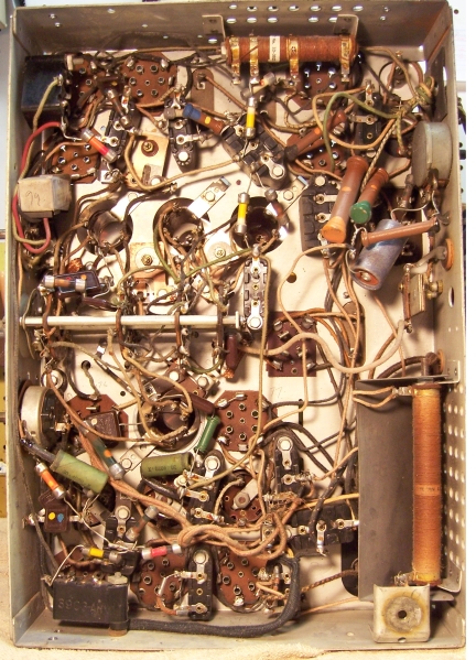
Chassis Before Restoration
|
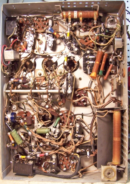
Chassis After Restoration
|
 |
 |