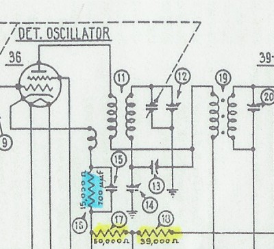
Philco 32 and 89 Oscillator Circuit
My antique radio restoration logs
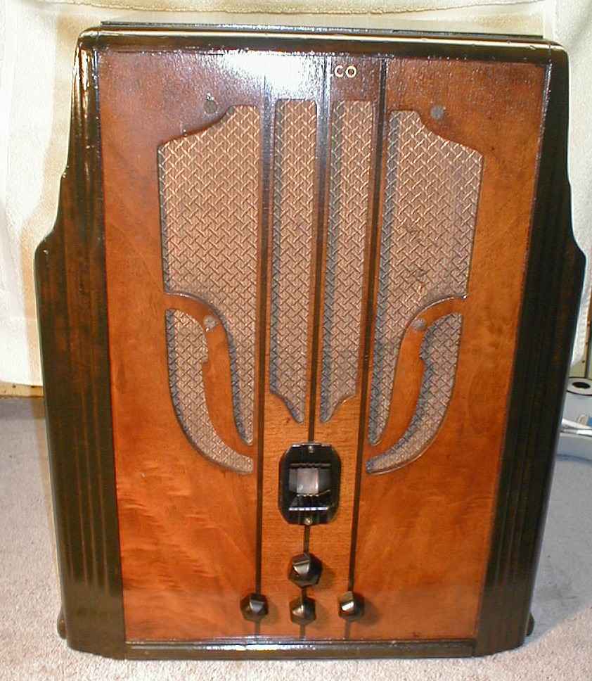
This radio was purchased on eBay as not working, and obviously missing all tubes and tube shields. I was told that it is a relatively rare set, being a Philco and a 32 volt farm radio. Most 32 volt radios I have seen were made by Delco, Silvertone, Coronado (Wells-Gardner), Parmak, Crosley and Universal Battery Company. 32 volt radio sets were used in rural areas before electrification. Some farms had complete 32 volt DC power systems for lamps, fans, farm machinery, appliances such as toasters, and of course radios. 32 volt house wiring, lamp sockets, and receptacles were the same as those used for today's 120 volt AC power. This was done because they knew that eventually they would get high-line AC power (Rural Electrification Act of 1936), and thus would not have to rewire the house! The 32 volt DC power originated from batteries, usually a bank of 16 2 volt wet cell storage batteries. These could be charged by a motor generator set, or even by wind power (Zenith Wincharger). Many of these types of radios are found destroyed because sellers will plug them into a 120 volt socket to "test" them prior to sale.
There are several types of 32 volt radios. One type uses 32 volts for the set's high voltage supply, as well as for the filament supply for the tubes. These types of radios typically use parallel or push-pull output tubes to overcome the low B+ supply. The RF, IF, and low level AF tubes seem quite happy with 32 volts on the plate. A commonly used output tube is the type 48, which has a 30 volt 0.4 amp filament. These tubes are most often found burned out since they are directly across the line and someone usually has plugged the set into 120 volts in its lifetime. Another type of 32 volt set uses a vibrator power supply like used in early car radios and in 6 volt farm radios. A vibrator chops the 32 volt DC into "AC" and a transformer steps up the voltage. The vibrator may also rectify the resulting high voltage AC, or a separate tube rectifier may be used.
The Philco 32B uses a vibrator with a separate tube rectifier. But the power supply is very large and heavy! I was really curious why. When opened up, the vibrator and transformer were massive. Looking at the schematic in Riders revealed the answer: the vibrator transformer not only supplies the high voltage, but also supplies the filament voltage for the type 84 rectifier! I have never seen such a configuration before. So I was determined to get the radio working. See http://www.nostalgiaair.org/PagesByModel/184/M0013184.pdf for the schematic on Nostalgia Air.
The Philco 32B is basically a modified Philco 89. The set has 5 tubes plus rectifier, and has an RF amplifier stage. It receives the broadcast band (520-1500 kHz) and also has a "police/aircraft" band. There is no dial scale for this band, but it was later determined that the coverage is 1300-3260 kHz. The main differences between the Philco 32B and the 89 are:
When I unpacked the radio and looked under the chassis, my heart sank: the oscillator coil was missing. Also, the wires to the volume control were all disconnected. The good news was that the remainder of the set was virtually all original. I could find only one component that had ever been replaced. Before proceeding with the restoration, I took another look at the schematic. While the radio has two bands, I noticed that the oscillator coil was NOT switched between broadcast and police. What's up with that? After some head scratching, I finally figured out that on the police/aircraft band, the second harmonic of the oscillator is used. Since the IF frequency is 260 kHz and the broadcast band (according to the dial markings) covers 520-1500 kHz, this means that the oscillator always runs from 780-1760 kHz. If doubled, and maintaining the 260 kHz IF frequency, the police band coverage would then be 1300-3260 kHz, which checks out with Riders. So the good news is that no complex tapped oscillator coil would be needed. However, again looking at the schematic, the converter stage is weird. It uses a type 36 tetrode rather than a more normal 6A7. And the coil (part #11 in the schematic has THREE windings:
|
|
Philco 32 and 89 Oscillator Circuit |
My repair strategy was to attempt to use a universal replacement oscillator coil - the P-C70-OSC coil sold by Antique Electronic Supply. This coil is slug tuned so that its inductance can be adjusted. It has a tapped secondary as would be used for a 6SA7 type converter tube, and also has a separate feedback winding as would be used with a 6A7 or 6A8 type converter tube. I figured I would first attempt to get the radio functional with the existing type 36 converter tube, but if all else failed I could replace the tube socket and use a 6A7 tube. Looking through Riders, I found a circuit which has some chance of working with the existing type 36 tube and P-C70-OSC coil: the Philco model 59. That set uses a type 77 converter (later versions of the Philco 89 also used the 77), and an oscillator coil with only two windings - like the P-C70-OSC:
 |
|
Philco 59 Oscillator Circuit. Trimmer #8 has 2 functions: it couples the plate circuit to the coil for feedback, and also resonates the primary of the first IF transformer 13 to 260kHz. |
So I decided to try this circuit first, but using the existing type 36 tube rather than a type 77 (I would have to change the socket to a 6-pin type). I would make one change, however. I would place the broadcast padder (Philco 32 part #14) in series with the cold (ground) end of the coil (#7 in the Philco 59 schematic)..
Now that I had a repair strategy, I would proceed with the restoration. My normal electrical restoration procedure is as follows:
All paper and electrolytic capacitors would be rebuilt in their original containers in order to maintain both above and below chassis appearance.
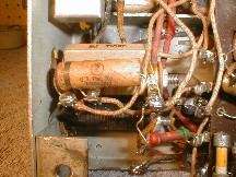
The speaker field was OK. The output transformer was OK. I next opened up the large, heavy power supply box. The windings of the power transformer checked out OK. The type 84 rectifier was intact inside the case, and was good. The vibrator operating coil showed a high resistance - uh oh! So I opened up the vibrator unit to examine it (unlike most vibrators, this one can be completely disassembled by removing screws). Measuring the vibrator coil directly, it checked out OK. So the problem was with the vibrator contacts. I cleaned all the contacts with 600-grit emory paper followed by Deoxit and spray cleaner. Still no luck. I did some adjustment on the contacts so that power could go to the operating coil. I then applied 32 volts to the unit. It still did not vibrate. But if I STARTED it manually, it WOULD vibrate. Not only that, the type 84 rectifier lit up and plenty of high voltage was developed! After much more adjustment of the contacts, the vibrator would start on its own and work. The power supply was later recapped (all capacitors were rebuilt in their original cases).
 |
|
Power Supply Guts after cleaning and recapping |
 |
|
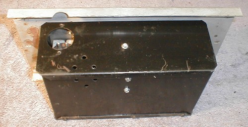
Power Supply enclosure - it has rubber shock mounts to the cabinet mounting plate. The power cable to the radio plugs into the hole on the left side. |
Survey (refer to http://www.nostalgiaair.org/PagesByModel/184/M0013184.pdf)
Item #1 - Oscillator Coil.
 |
|
Replacement oscillator coil in place with fabricated bracket. |
Item #5 - Bad Ground. The bad ground was repaired by adding an adjacent ground lug with a Philco type hex self-tapping screw through an extant hole near the type 36 tube socket. The components and wiring were moved to this new ground lug.
Item #4 - Open Detector Coil. The detector coil (part #8) was successfully repaired. The tuned secondary was open. The primary was OK. The secondary is tapped at about 25%. The upper 75% is shorted out by the band switch when the police/aircraft band is selected. The entire secondary is used for the broadcast band. The break was between the tap and the cold end of the coil. As luck would have it, that section of the coil was covered up by the PRIMARY winding. To repair the break, I had to first remove the primary winding. I first removed the winding, carefully noting the number of turns, position on the coil form, and (important) winding direction. The winding had 13 turns, and was separated from the secondary by a piece of plastic film. I then removed the plastic film (with help from a heat gun). Once the secondary was exposed, I noticed several green spots on the winding - the likely failure points due to corrosion. I then unsoldered the cold end of the coil and started unwinding the coil, noting the number of turns removed. The first break was 19.5 turns up from the start. There were 2 breaks. I then scraped, tinned, reconnected and soldered the wire at the break and rewound the coil. I figure I lost about 1-2 turns, but assumed that could be compensated by the trimmer capacitors. I replaced the plastic insulator with a piece of masking tape, then rewound the primary coil - again carefully positioning it on the form in the original position, and winding in the same direction as the original (I found out the hard way on a previous restoration that if the winding direction of the primary is reversed, oscillation may result). After the repairs were made, the coil check out OK. I covered the coil with rosin (salvaged from RCA catacomb sets) to seal the windings and hold them in place. The coil was then re-installed in the radio.
Item 17 - Open Bias Resistor. The 235 ohm section of the bias resistor #52 was open. The 32 ohm section was OK. I first removed the resistor from the set, and then carefully removed the cord Philco used to cover the actual resistance wire (never could figure out why they did this!) The break was not obvious. So I started unwinding the resistance wire. It was broken in several places. I did not have a resistor in stock to replace it. So I removed all the old resistance wire and temporarily shunted at 250 ohm 3 watt resistor across the terminals. Later, I plan on ordering a 300-500 ohm 20 watt adjustable resistor with a tap to replace the existing resistor (I realize it does not need to be 20 watts, as there is only about 17 volts across it, but I need something that is similar in size to the original). I do not trust the existing resistor, since the 32 ohm section could open up at any time.
 |
|
Bias resistor repair. |
Item 18 - Speaker cone. The tears in the speaker cone were repaired using Service Cement, available from Antique Electronic Supply.

Item 21 - Capacitor #2. Bakelite block capacitor #2, as well as #39 were rebuilt in their original cases. They were first removed from the set, the sealing tar chipped out, the capacitors removed from the cases, then the cases were cleaned using lacquer thinner. Capacitor #2 was a Philco type 4989G (dual 0.09uf). This was rebuilt using 2 0.1uf/630 volt modern tubular capacitors. Capacitor #39 was a Philco 4989AL (0.01uf). It was rebuilt using a 0.01uf/630 volt modern tubular capacitor. The sealing tar was not replaced.
Paper Capacitors: In order to maintain original under chassis appearance, paper tubular capacitors were rebuilt in their original cases. In this set, all paper capacitors had crimped ends, which cannot easily be taken apart for rebuilding. I simply cut off one end of the crimp flush with the cardboard end cap using a sharp razor blade. I then pulled out the wire and end cap on that end. I then applied heat from a heat gun to allow removal of the capacitor inside, and to clean up the outside of the case. The other crimped end was left undisturbed with the end cap in place. I then removed any residual wax inside. I then wrapped the replacement tubular capacitor with a piece of paper towel cut to the proper width until it would fit snugly inside the case. The replacement was then installed, one of its wire leads threaded through the end cap on the undisturbed end. I then melted some rosin (salvaged from RCA catacomb repairs) into the open end of the case, and while still liquid, re-installed the other end cap (cardboard). The rosin held the cap in place. It is difficult to tell that the capacitor has been repaired.
Filter Capacitors: Filter capacitors #49 and #50 were also rebuilt in their original cans. Philco caps are easy to rebuild, since in this case both had a cardboard sleeve covering all or part of the aluminum can. The capacitors were first removed from the set. The cardboard sleeves were removed. The capacitor was held in a bench vise and a cut made with a hacksaw about 1/2" above the bottom of the capacitor. One of the capacitors was a wet type, so a tray was used to catch the liquid still inside. The insides were removed in both cases, and the cases cleaned and dried. For the dry capacitor, a hole was drilled beside the extant positive terminal and the plus lead of the replacement capacitor threaded through and attached to the terminal. The negative lead was extended, insulated with spaghetti tubing, and routed out the side of the capacitor to the existing negative terminal (which is not attached to the capacitor, but rather held in place by the insulating sleeve). For the wet capacitor, a hole was drilled into the aluminum extension of the positive terminal post and a ground lug attached using a 4-40 screw and nut. The replacement capacitor was then soldered to this lug. The negative lead of the replacement was treated as described above. I used 10uf/450 volt electrolytic capacitors for both. The cardboard sleeves were then reinstalled (in the case of the capacitor with the short sleeve, epoxy was used to hold the top portion of the capacitor firmly inside the sleeve). These sleeves held the negative lugs in place. The capacitors were then re-installed in the chassis, carefully noting the direction of the negative terminals.
Tone Control: The tone control switch (#40) was removed from the chassis and the two capacitors (#41) replaced. These capacitors were embedded in tar and are part of the tone control switch assembly. Once the ground connection and connection to the tone switch was unsoldered, the capacitors and their container (sealed in tar) could be removed as a unit. The outside insulating paper was removed and reused. New capacitors were installed (0.01uf and0.015uf/630 volts). A new wire lead was also installed since the existing wire was rubber covered and crumbling. The capacitors were covered with rosin to seal them and keep them in place.
Here is a photo of the completed chassis. The repairs are hard to spot!

Here is the above chassis view - the tube shields have not yet been installed.

Once all repairs had been made, it was time for a test. The power supply and speaker were plugged in. The radio was plugged into my 32 volt power supply. I connected an antenna wire to the antenna terminal, but did not expect any reception, at least initially. When power was applied, the radio came alive. There was a horrible squeal when the volume was advanced. I had to install a temporary tube shield on the type 75 detector/first audio to stop it. A quick check revealed that all filaments were lighted correctly and B+ was normal. When the volume was advanced, I was surprised to hear some static! When the tuning control was turned, the set actually was receiving a station! This meant that at least the oscillator circuit was working (but likely not at the correct frequency). I next attached a frequency counter to the cathode of the 36 tube. I found that the oscillator was running at 1.7mhz with the tuning cap at minimum - close to the correct frequency. But the reception was very weak, and there was no reception at the low end of the dial.
Next, the IFs were aligned at 260kHz. Both peaked nicely, and were WAY OFF as found. After this, reception was much better. The stations were not coming in at the correct dial position. So I next tried adjusting the slug in the oscillator coil as well as the series padder until stations at the low end of the dial came in close to the correct frequency (I use an old Radio Shack DX440 digital radio to determine the frequency of any stations I find). I then adjusted the oscillator trimmer on the tuning capacitor until the stations on the high end of the dial come in close to correct. I repeated this exercise several times, and the result was that stations came in close to the dial markings on both ends of the dial, and the radio was quite sensitive. It even received a couple of stations on the police band (which has no adjustments). I could not hope that the replacement coil would track the dial scale as well as the original. Finally, the antenna and detector trimmers on the tuning capacitor were peaked at 1400khz.
The volume control worked OK, so the value must be correct even though it differs from the schematic.
I plan on leaving the radio as is until I can acquire a junker Philco 32, 89, or 19 chassis with a good oscillator coil, and if available, a bias resistor #52.
Photos of completed set below. Plays great! Sounds great!
I was able to purchase a junker parts chassis for a Philco 89 Code 123 on eBay for under $10. It yielded the missing oscillator coil as well as the wire wound bias resistor #52. The oscillator coil feedback winding was open, which is usual. But it is on the outside, and had only 26 turns. I rewound it with #36 enamel wire (the original was I think thinner and cotton covered). But since it is a feedback winding and not tuned, I figured it was not that critical. I also took the time to restore the oscillator coil wiring back to original using wire from the Philco 89. The result was that it worked well - the same as before, but is now more original! I'll keep the parts chassis as a source of Philco tube shields, bakelite block capacitors, and other parts for future repairs.