Underside of chassis before restoration
Underside of Chassis After Restoration


My antique radio restoration logs
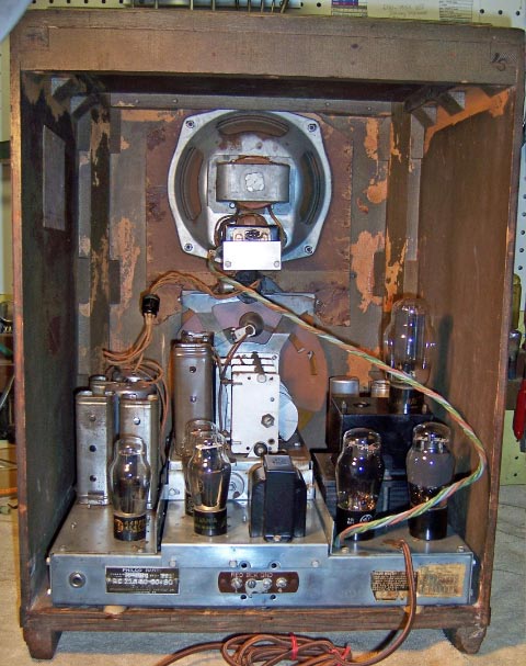
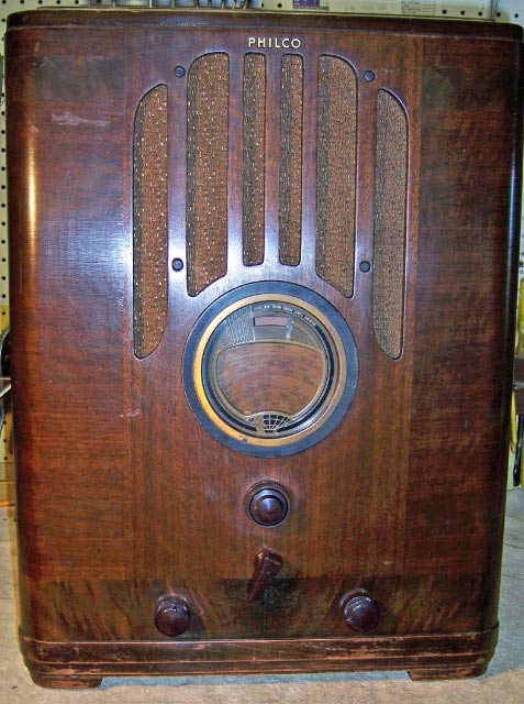
The Philco 37-2670 is a large tombstone style radio with 11 tubes and 5 bands (including the Long Wave band used in Europe). It operates from 120 or 240 volts (the line voltage is selected by moving a plug on top of the power transformer). It has push-pull triode connected 6F6's in the output stage operating in class AB2. The large solid cabinet and electrodynamic speaker deliver great sound. It has a tuned RF stage. The most difficult part of the restoration was obtaining the correct "G" type tubes used by Philco, including 5 6J5G's! The radio as found was missing several tube shields, and was fitted with a combination of metal and GT type tubes, which are not correct. There was one tacked in filter capacitor, and the line bypass capacitor and line cord had been replaced. Other than those items and the tubes, little else had been done to the radio.
I take high resolution photos of the underside of the chassis in order to check my work and also to reproduce component mounting and lead dress (critical in some radios). My objective: one should not be able to see the repairs made. All bakelite block as well as tubular capacitors and filters were rebuilt in their original cases. Tubular capacitors were resealed with rosin salvaged from servicing RCA Radiola Superhet catacombs. Some wiring had to be replaced, unfortunately.
|
Underside of chassis before restoration |
Underside of Chassis After Restoration |
|
|
Below: Chassis Top after restoration. Transformers and choke were removed and repainted. Chassis was cleaned with GoJo and steel wool. Some rust was removed.
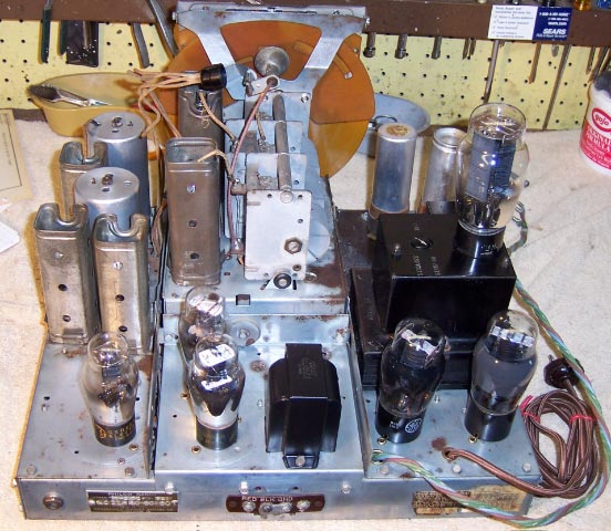
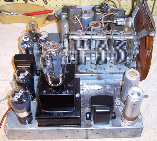
Below: Chassis Top View after Restoration. Side View.
Below: Chassis Top View after Restoration. Side View.
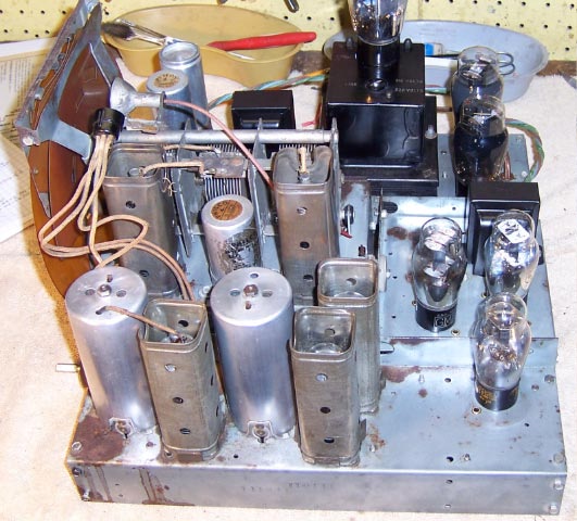
Below: RF Sub-Chassis Before Restoration. The band switch shaft was removed and then the individual sections were disconnected and removed for restoration. Unless this were done, some of the components could not be replaced without difficulty.
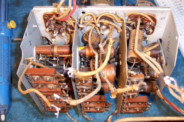
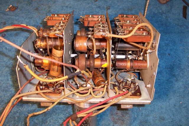
Below: RF Sub-Chassis After Restoration. Several resistors were replaced, and all tubular capacitors were rebuild in their original cases. Any mica capacitors that could be disconnected for testing were tested. The switch sections were cleaned while apart.
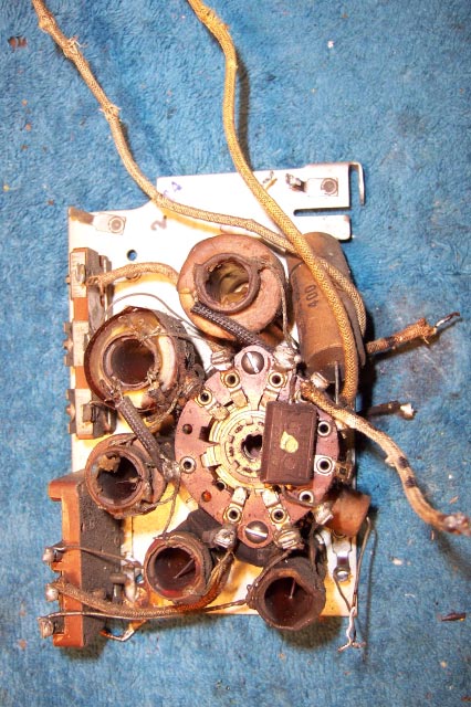
Below: Typical Section of RF Subchassis Removed for restoration. Note the parts buried within the bandswitch.
Below: Completed Restoration - Front: The grille cloth is a reproduction. The finish and knobs are original. The shadow tuning meter works perfectly.
Below: Completed Restoration - Rear View