Philco Model 37-61 Restoration
 |
The Philco Model 37-61 is a 5-tube AC superhet circuit
radio. It receives the standard broadcast band and one short wave
band. The circuit is conventional. This radio had seen some
servicing in the past but had not been hacked excessively. This
being the case, I decided to try and retain/restore the original top and bottom
chassis appearance if possible.
Previous servicing included several replacement tubes, a new line cord
and plug, a hole-filler filter capacitor installed (but no tacked in
filter cap to replace it), and a replacement on-off/tone switch (replaced
by a standard potentiometer and switch). One very worrying item was
noted: the metal cap that retains the type 5Y4G tube socket on top of the power
transformer had been removed (tabs damaged) and was loose. All original wax-paper and bakelite block capacitors
were intact.
The schematic for the Philco 37-61 can be found on Nostalgia
Air. Any part numbers will refer to numbers on that schematic. |
My
antique radio restoration logs
Survey
My usual restoration procedure is to first make a complete
survey of the condition of all components. The survey results guide my
restoration strategy. If major and unique components are defective and
cannot be restored, I may elect to sell the radio rather than restore it.
I assume that all paper and electrolytic capacitors are leaky and thus should be
replaced (I always "restuff" the original containers if possible).
-
The on-off switch and tone control switch (Part 47) had been replaced
by a potentiometer with switch.
-
It appeared that someone
had removed the cap that holds the 5Y4G rectifier socket on top of the
power transformer. The power transformer was immediately suspect and was
carefully checked. First, I measured the resistance of all windings -
all were reasonable. Then I connected the primary to AC through a
fused variac and watt meter. Starting with 20 volts, winding voltages were
measured. At full line voltage the wattage was minimal - about 5
watts. The two halves of the high voltage winding were within a few
volts of equal. Filament voltages were also OK. The transformer did not heat up.
But once the power supply section had been rebuilt, I once again applied
power through a fused variac and watt meter and this time measured the
B+. It was then I noticed that if the rectifier tube were moved
slightly, the B+ went to zero and the watt meter shot up. So there
was a short somewhere inside the power transformer. That's no doubt
the reason that the cap had been removed.
-
There were also several
wires that had been disconnected in the power supply area.
-
One filter capacitor (Part 44) had been removed and replaced
by a hole-filler of similar size, but of the wrong type (lead wires, which
were CUT, vs. a central terminal). The original
insulator was not present (this capacitor is not grounded to the chassis).
Wiring that should have gone to the ground lug of this capacitor was loose
and not connected. No tacked-in tubular replacement was
installed. Looks like an attempted restoration by someone who was
confused and gave up!
-
The 5Y4G rectifier tube was missing. An 6V6GT was
installed in place of a 6F6G.
-
The AC line cord was OK but not original - black vinyl (it
should be brown rubber zip cord).
-
All coils and transformers were OK with the exception of the
short-wave oscillator coil (Part 10).
-
The speaker field and cone were OK.
-
Five resistors were out of tolerance by 30% to 60%.
All but one were dogbone types.
-
The wire wound bias resistor (Part 43) was fortunately good.
Repairs
Power Transformer
The wires to the (now loose) rectifier socket were unsoldered and the socket
and insulator sleeve removed. The top cover of the power transformer was
then removed. It was immediately obvious what the problem was: one of the
rectifier filament leads had worn insulation and signs of burning. The
inside of the transformer shell indicated arcing and burning. For a
repair, the filament
leads were covered with spaghetti tubing and the inside of the transformer shell
was insulated with black electrician's tape - several layers on both sides (the
high voltage side and the filament side). The top cover, socket, and
insulator was then reinstalled. The socket cover was reattached to the
transformer cover using epoxy and small self-tapping screws. Subsequent
testing indicated no further problems with shorts. It is REALLY amazing
that the power transformer survived this short. Perhaps it was saved by
the 5Y4G rectifier tube, which suffered a direct short from B+ to ground.
Capacitors
All paper and bakelite block capacitors were rebuilt in their original cases
using modern 630 volt film capacitors in order to maintain the original
under-chassis appearance.
The two original can type electrolytic capacitors (Parts 20 and 42) were also rebuilt in their
original containers. The cans were cut most of the way through on a Unimat lathe and the cut
was completed using a hobby razor saw. The cuts were near the base in both
cases so that the joint would be hidden by the clamps or insulating cover.
The original contents were removed, the cases cleaned, new 450 volt
electrolytics installed inside, and the two halves of the cans joined using
3/4" PVC
plumbing couplings and epoxy. The non-original hole filler filter
capacitor (Part 44) was removed and replaced by a Philco capacitor with insulator from a donor
Philco Model 89 chassis. The replacement was rebuilt as discussed above.
Resistors
All original resistors more than 20% out of tolerance were replaced. I
used dogbone type resistors as were used originally. One resistor in the
RF subchassis (Part 13) was an old style carbon composition type - it was replaced by a
very similar type that was within 20% tolerance. I picked out NOS and used
dogbone resistors that had drifted to the correct needed resistance and then repainted them to
match the original resistor's color codes. The replacements may continue to drift, as would most new carbon
composition type resistors. But to me, maintaining the original look is
more important than long term reliability of the radio.
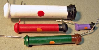 |
Here are the four replacement dog-bone
resistors, ready for installation in the radio. The 9K 2 watt (Part
19) was
marked 13K, but actually measured 8.8K! The 20K 1 watt (Part
18) was
originally 15K. The 70K 1/2 watt (Part 34) was originally 50K, and the 51K 1
watt (Part 25) was originally 32K. All have been repainted using hobby paint. |
AC On-Off and Tone Switch
The original AC on-off switch and tone control switch (Part 47) had been replaced by a
standard potentiometer and switch. The original was a three-position
rotary switch. Position 1 was AC OFF. Position 2 was AC ON, and
position 3 was AC ON with the tone switch contact closed (bass position). I placed
a wanted Ad on the Philco
Phorum Wanted List and also checked with Gary Schneider at Play
Things Of Past - no luck. So I decided to install a 2-pole 3-position rotary
switch until the original part could be found. In the process of searching
through my stock of rotary switches, I found something very close to the
original part! Other than the shaft length (it was too long), it had all the
functionality of the original - how's that for luck!
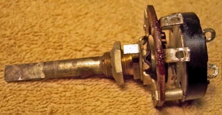 |
Here's the switch I found in my stock of rotary
switches. It looks very similar to a photo of a an original switch,
the repair of which was discussed on the Philco
Phorum. I'm guessing that it is an
original switch, but for a different Philco radio that required a longer
shaft length. The switch was also GOOD. All I had to do was to
clean it up, cut the shaft to the proper length, and file a notch for the
knob. |
RF Subchassis Repairs
The RF subchassis was removed from the radio for rebuilding. The tuning
capacitor was removed for cleaning and lubrication. The two-speed dial
drive assembly was removed, disassembled, cleaned in lacquer thinner, greased,
and reassembled. The tuning capacitor bearings were lubricated with
lithium grease. The filter capacitor (Part 20) was removed for restuffing.
The bandswitch and coil assembly was removed in order to gain access to the
screw that holds the short wave oscillator coil (see next section). The
bandswitch was cleaned using Big Bath spray cleaner. The rubber mounting
grommets were replaced by new reproductions from Renovated
Radios - part PHG-RF.
Short-Wave Oscillator Coil
The feedback winding of the short-wave oscillator coil (part 10) was open.
The coil was first removed from the RF subchassis. To do this, the
bandswitch and coil assembly must first be removed from the RF subchassis to
gain access to the screw that holds the coil. Once the coil was removed,
it was obvious that the feedback winding was on the INSIDE of the form, on
another smaller form. This form did not go all the way through the outside
form. Also, one of the leads from the outside winding (heavy wire - about
#20 or so) passed through both forms. This lead was pulled back through
both forms and secured with tape to prevent the coil from unwinding.
A pencil soldering iron was then inserted into the center of the inner form
and moved around until the wax started to melt on the outside form. At
this point, I was able to insert a screwdriver into the bottom of the form and
push out the inner form. The typical "green" Philco disease
(corrosion due to moisture) was then obvious on the feedback coil. I began
unwinding the coil hoping for a single break, but almost every turn was
broken. So I removed the winding completely and replaced it with #38 DCC
magnet wire. The wax impression of the original coil indicated correct
number of turns, the spacing, and winding direction.
Once the new coil was rewound, it was sealed with rosin and then reinserted
into the outer form. The trick here is to align the holes where the lead
from the outside coil passes through both forms!
Other Repairs
- The RF subchassis rubber grommets were replaced. These grommets are available from Renovated
Radios
- The chassis was cleaned using GoJo and steel wool, tooth brushes, small
bottle brushes, and pipe cleaners.
- The bandswitch was cleaned using Big Bath spray
cleaner.
- The line cord was replaced with a brown vinyl cord, which would be closer
to the original rubber cord.
- Correct 5Y4G and 6F6G tubes were installed.
Testing and Alignment
Once the radio was reassembled and tubes installed, power was brought up
slowly using a variac. AC power was monitored using a watt meter, and a
DVM monitored the B+. The radio came alive immediately and worked.
Once at full power, voltage measurements were taken.
The set was aligned - no surprises.
Restoration Results
Restored Chassis

Rear View
