Philco Model 38-9 Restoration
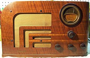 |
The Philco Model 38-9 from 1938 is a 6-tube AC Superhet
circuit radio that
receives the broadcast band and one short wave band. The radio had been serviced in the past but most
of the original
parts were still in place. I
decided to try and reverse all prior servicing and restore the original chassis appearance if
possible. The schematic can be found on-line on Nostalgia
Air. Any part number references in the text below reference that
schematic.
|
My
antique radio restoration logs
Overview
The radio was purchased on eBay and was said to power up and
hum, but no reception (very likely the seller did not connect an antenna!). The radio appeared complete and in good condition.
The radio is a 6-tube superhet that receives the broadcast band and one short
wave band. Although it has 6 tubes, the circuit uses two tubes for the second
detector/AVC and first audio amplifier, when both functions could have been
performed by a single 6Q7G tube - tube count inflation! Features include a
two-speed tuning control and three-position tone control combined with the
on-off switch.
Previous Servicing
I always attempt to avoid purchasing radios that have been
"restored" by collectors or flippers, and am looking for either all
original examples or those which have been "lightly serviced" in the
distant past by radio service shops, rather than peppered with new film
capacitors. This radio had received some prior
servicing, but had not been badly hacked or restored. Most of the original
parts were still in place, including both filter capacitors..
- The 5Y4G tube was branded Philco and may have been original. The 6K7G and
6F6G were branded Sylvania and may have been original. All the rest of the
tubes were replacements.
- In 1938, Philco, like Zenith used only G type tubes with shields where
needed. Metal tubes or GT types cannot be used, since the shield base
internal diameters are too small to accept these tubes. Unfortunately, many
service shops at the time did not stock G type tubes, preferring more modern
metal or GT types. It was very common to find the shield bases bent and
damaged so that these tube types could be used. In this radio, the 6J5G and
6K5G bases had been damaged and GT type tubes used. The 6K7G shield
base was OK, and a G type tube installed (likely original - branded
Sylvania).
- The AC line cord was likely original, but was rotted and spliced to a
length of twisted cloth covered wire. A large clamp type heavy duty plug was
installed.
- A phono input jack had been added, connected using a length of shielded
wire (fortunately, no holes were drilled into the cabinet or chassis!)
- The wire leads to filter capacitor 11 and 11A had been cut and two tubular
electrolytics tacked in under the chassis. Filter capacitor 45 was still in
place and leaking. No replacement had been installed for this
capacitor!
- Three wax-paper capacitors had been replaced: parts 24, 28, and 38. A
0.1mfd capacitor had been added which connected the 6K5G audio amplifier
grid directly to the cold end of the second IF transformer, thus bypassing
the volume control! I have no idea why this was done, unless it
somehow related to the added photo jack. All remaining wax-paper capacitors and all resistors were original.
- Several capacitors and one resistor had been moved and their location no
longer agreed with the Philco parts placement diagram. In one case, the
resistor 36 looked original and this may have been a production change. I
left this resistor in the as-found location (it had to be replaced, since it
was out of tolerance).
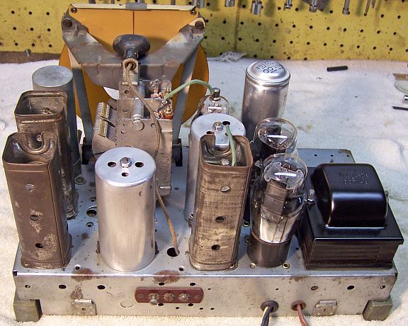
Cleaning
The chassis was dusty, very dirty and had a few rusty areas. All tubes
and shields were removed. The dust was vacuumed
and blown off, top and bottom using an air compressor. After removal of
filter capacitors 11/11A and 45 (for restuffing) and the tuning capacitor and
dial assembly, the top of the chassis was cleaned using GoJo (white) hand
cleaner and 00 steel wool.
Survey
-
The speaker cone, field coil, and output transformer were
OK.
-
All coils and the IF transformers were OK.
-
The power switch (combined with the tone control switch) was
bad. Likely the contacts had oxidized or were dirty. A shot of GC Big
Bath spray followed by repeated operation of the switch cleared up the
problem.
-
The tuner reduction drive was not operational (likely due to
hardened grease).
-
The tuner anti-backlash mechanism springs were not in
position which caused the tuner to jam at some point in rotation.
-
The power transformer was OK. The high voltage winding was balanced
on each side of the center tap with 10 volts applied to the primary through
a variac. It drew less than 10 watts at full line voltage (unloaded), and
all filament voltages were correct. I always make this test prior to
restoration, since some transformers may have shorted turns which may result
in overheating with usage.
-
One section of the wire wound resistor 43 (Candohm type)
measured 37% high and the resistance was unstable (it changed when the lugs
were
moved). The remaining two sections were OK.
-
Tubes: the replacement 6A8 (metal) was bad. The likely
original 6K7G and 5Y4G were good. The likely original Sylvania 6F6G was very
weak. The replacement 6K5GT was shorted, and the replacement 6J5GT was very
weak. The 6A8, 6J5, and 6K5 should be G type tubes.
-
The shield bases for the 6J5G and 6K5G had been severely
damaged in order to install GT type tubes.
-
The speaker cable was frayed and bare near where it enters
the chassis.
-
The 6K7G grid cap lead was frayed where it entered the top
of the IF transformer.
-
Five resistors were out of tolerance (more than 20%).
One (part 12) was a 3-watt dogbone type. The remainder were carbon
composition types.
-
The dial lamp was OK.
-
The line cord was rotted and unsafe. The original plug was
long gone, and a length of heavy twisted cloth covered heater wire spliced
onto the existing cord, terminated by a large appliance plug.
-
A phono jack had been connected between the second detector
grid and ground using a short length of shielded wire.
-
The tuning capacitor rubber mounts were shot, permitting the
tuner and dial to move around excessively. Fortunately reproductions
of these complex parts is available from Renovated
Radios.
-
Several of the rubber chassis corner supports were also shot, which meant that
the control shafts were not properly centered in the cabinet. Again,
reproductions of these parts are available from Renovated
Radios.
Restoration Strategy
I assume that all paper and electrolytic capacitors are leaky and thus should be
replaced. I
do not replace mica capacitors, but may test them in place if possible (usually
this requires disconnecting one lead of the capacitor). When I replace a component, I
always remove the original part and any wire fragments completely from a terminal. Other good components connected at the terminal are protected from heat using old medical
clamps (hemostats). Excess solder is then removed using a solder sucker in order to
expose terminal holes for reattachment of the rebuilt or replaced component.
Since almost all of the original parts were still in place I decided to try
to maintain the
original chassis appearance to the extent possible. Normally I rebuild all original wax-paper capacitors as well as the filter capacitors in
their original cases (restuff them). Both filter capacitors were still intact and could be
restuffed.
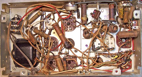
Repairs
One must be VERY CAREFUL when doing repairs in the area of the
band switch. The leads from the antenna and oscillator coils to the band
switch are hair thin and very fragile! There are several capacitors in the area
which have to be changed. Before starting repairs I took photos of the
chassis, top and bottom, so that the original component placement and lead dress
could be maintained.
Wiring
The first IF amplifier grid cap lead was worn and could short
to the transformer shield. This lead was replaced. To do so, the grid cap
was removed and the transformer shield removed. The transformer itself and
associated wiring was left in place. The grid lead was replaced using
green stranded hookup wire. The new lead was left long so that it could be
routed through the small hole in the top of the transformer shield as the shield
was being replaced. The shield was reinstalled, the lead cut to the
correct length, and the grid cap reinstalled.
The speaker cable (3 leads) was very stiff and there were
breaks where the cable passed though a hole in the rear chassis. The
clearance hole had no fiber grommet, unlike the hole for the power cord.
Perhaps it had broken. A vinyl grommet was installed just in case. The
speaker cable was removed from the radio and pulled out toward the front of the
chassis. The knot was undone and the cable leads straightened. I
used a heat gun on the cable to make it more flexible during the straightening
process. The leads were separated and patched using shrink tubing. The twist and
knot were restored and the cable reinstalled in the chassis, passing through the
vinyl grommet for some protection.
The line cord was replaced by a new brown vinyl cord with
molded plug. The original cord was a darker brown rubber.
Wax/Paper Capacitors
Three original Philco paper-wax capacitors had been replaced (parts 24, 28,
and 38 - all associated with the volume or tone control). I collect branded (Zenith, Philco, Sprague,
RCA/GE etc.) dud capacitors just for cases where an original
part has been replaced by a modern part. I was able to find the correct original
Philco part for 24 and 28 in my dud stocks. I did not have the correct original Philco part
for 38 (30-4467, .006mfd/600 volts), so I used Philco part 30-4591 (.006/400 volt) to
replace it. All paper-wax capacitors were restuffed using 630 volt film
capacitors. Capacitor 30 had been moved to the opposite side of the
chassis. After restuffing it was returned to the location shown in the
parts placement diagram.
My re-stuffing process is as follows:
- The original capacitor is removed from the radio, and the required lead
length and any insulating sleeving use noted.
- The low melting point wax from each end of the original or replacement
capacitor is melted and removed using an old
25 watt soldering iron.
- The original wire leads are removed, as well as any remaining wax.
- While the internal wax is still molten, a small screwdriver is used to push out the
original paper-foil roll. In some cases, the contents comes out when the leads
are pulled out.
- The original cases are then cleaned out, and any wax and dirt on the
outside removed by gently heating the body over a small alcohol lamp and
wiping with a paper towel while still molten.
- If the required lead length is longer than that of the replacement
capacitor, a piece of buss wire is attached before restuffing. The splice is
hidden inside the tube.
- The replacement capacitor is wrapped in a narrow strip of
paper towel in order to keep the new capacitor centered and to keep it from falling out.
- The finished capacitor is then sealed with melted rosin salvaged from
early RCA Superhet catacombs, and donated by or purchased from members on Antique
Radio Forums. I do NOT recoat the outside of the rebuilt
capacitors with wax (I'm not sure what was originally used - probably
beeswax).
Some original capacitor values are no longer available. In these cases I used
the closest current value. I did not try to use multiple capacitors to get
closer to the original values, since there was no room inside the original
case. For C40, 0.008mfd I used 0.0068mfd. For C38, .006mfd I used 0.0056mfd.
For C37, .03mfd I used .033mfd.
Filter Capacitors
The original power supply filter capacitors 11/11A and 45 were removed and restuffed.
Part 45 (30-2219A) was a 25mfd 475 volt wet electrolytic. It was restuffed
using a 22mfd/450 volt axial tubular electrolytic. My restuffing process for
this capacitor is as follows:
- The capacitor was mounted in my small Unimat lathe by holding the bottom
end in the 3-jaw chuck and retaining the opposite end using the lathe's live center
(centering it so as to ensure smooth rotation).
- The case was scored about 1" above the screw base (so that the
cardboard insulating cover would hide the joint). I finished
the cut with a fine tooth hobby razor saw - since these types of capacitors may still
have liquid electrolyte inside! In this case, the capacitor was dry.
- The center electrode was removed as well as the deteriorated rubber insulation and
external terminal lug.
- I used a small wooden spacer to replace the insulation. I had to
slightly enlarge the crimped end of the capacitor in order to insert the
spacer. For this, I used a succession of drill bits in my drill press. I then installed a long 6-32 machine screw from the terminal end,
through a solder lug, some fiber washers, through the spacer, through some
additional fiber washers, another solder lug, and finally a 6-32 nut.
The head of the machine screw was ground down so as not to be obvious.
The flattened screw head was then soldered to the outside solder lug, now
serving as the positive terminal.
- The plus lead of the replacement capacitor was attached to the internal
solder lug.
- The negative lead of the replacement capacitor was extended using solid
bus wire and insulating spaghetti tubing through a small drilled hole in the base
of the capacitor near the location of the original negative grounding lug.
- The two halves of the case were then reattached using 3/4" PVC
plumbing couplings and epoxy. If the cut is done cleanly, the cut is
hardly visible after reassembly. I had to add many layers of masking
tape around the PVC coupling to take up excess space.
- Once the epoxy has hardened, the original grounding lug and cardboard
insulator were reinstalled. The negative lead of the replacement
filter capacitor was then attached to the grounding lug. The cardboard
insulator completely hid the repair.
The process I used for restuffing the dry type capacitor 11/11A is similar to
the process used for part 45. However all of the contents have to be
removed, which is a messy and difficult process. I used a spade bit in my
drill press to remove most of the material. This capacitor is a dual dry type
capacitor with wire leads: 8mfd/475 volts and 4mfd/350 volts. It was restuffed
using a 10mfd/450 volt and 4.7mfd/450 volt electrolytic. The original
leads were cut, so they were replaced using the original wire colors. The
replacement capacitors were secured in the case using hot glue. The two halves
of the case were reattached with 3/4" PVC couplings as described above.
In this case no masking tape was needed, since the capacitor diameter is smaller
and the PVC coupling was a snug fit.

Resistors
One section of the three section wire wound resistor 43 (Candohm
type) measured 37% high and the resistance was unstable (it changed when the
lugs were moved). The remaining two sections were OK. This resistor is
used to provide bias voltages. I have found that these metal clad resistors
often respond favorably to clamping pressure near their terminals when a section
is unstable or has high resistance. I sometimes use a small C-clamp and
firm pressure on the metal housing on both sides near each terminal. In
this case, there was no way to use this method. I was forced to remove the
resistor from the chassis and apply pressure on both sides of the terminals
using my large bench vice. Each terminal is simply a band around the resistance
element, which is wound on an insulator. Over time, the band expands or
the insulator shrinks, resulting in an unstable, high resistance, or sometimes
an open section. In this case, after squeezing, all sections were almost
exactly correct and were stable (resistance did not change when the terminal lug
was moved)! Compressing the metal case applies additional pressure from
the band onto the resistance element. There is some risk to this
procedure, since the fish paper insulation may be damaged in some cases,
resulting in a short. For this reason, many collectors never re-use a
Candohm resistor in a restoration, even when good! Instead, they remove
the resistor and install terminal strips and individual wire wound resistors.
This of course greatly alters the under-chassis appearance of the radio. I
would also replace a Candohm resistor, and especially if part of it was bad, if
being PAID for a restoration. But this radio will be a keeper (which will
rarely if ever be played). And should the resistor eventually fail due to a
short or open, no major components would be damaged - the radio will simply stop
playing.
Resistor 12, a 10K 3-watt dogbone type resistor was out of
tolerance. I keep a stock of NOS and used "dogbone" resistors, and buy
all I can on eBay and radio swap meets! Of course, most of these
resistors, even NOS resistors, have also drifted in value and no longer have
their marked values. My solution is to find a replacement resistor of the
correct value and size as measured (ignoring the markings), and then repaint it
to the needed value codes using enamel hobby paint! In this case, I used a
6.2K 3 watt dogbone resistor that measured 9.24K. It was repained using
enamel hobby paint.
There were four carbon composition resistors also out of
tolerance. They are specified as 1/2 watt and are quite unique in appearance.
They are very close to the size of modern 1 watt carbon resistors. So I replaced
them with modern 1 watt carbon resistors and repainted them to match the Philco
color code scheme, which is body (1st digit), end (2nd digit), and a strip
(multiplier). In some cases, the body and stripe are the same color and no
stripe is used (490K). In other cases, the body and end colors are the
same (99K). I have always thought that Philco used these weird values in order
to avoid having to use a third color!
Here are the repainted reproduction resistors:

Tubes
The shield bases for the 6J5G and 6K5G were severely mangled in
order to install GT type tubes:
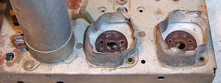
These were straightened as well as I could without removing the
shield bases, which would have meant drilling out the rivets. Fortunately,
the tube shields completely hide the damage. G type tubes were installed for the
6A8G, 6J5G, and 6K5G. The 6F6G was replaced (General Motors brand). The
original 5Y4G and 6K7G were good and were reused.
Tuning Capacitor
The dial assembly and tuning capacitor were removed for
cleaning, replacement of the rubber suspension parts, and repair of the
reduction drive. The two-speed reduction drive mechanism was removed from the
front of the capacitor. The trimmer capacitors and all associated hardware
(including the mica sheets) were removed before cleaning so that all parts could
be cleaned, and to avoid damage. The capacitor was then cleaned in my old
Heathkit ultrasonic cleaner using dilute ammonia. This has to be done in
several steps since the entire capacitor will not fit in the tank. Once cleaned,
it was rinsed and then cleaned with soap, water, and old toothbrushes and dried
using a heat gun.
As found, the anti-backlash gearing was damaged and was
preventing rotation of the tuning capacitor rotor. Originally there were two
driven gears. One was attached to the rotor shaft. The other was
free to rotate on the shaft. There were two small springs positioned between the
gears which put rotational pressure on the free gear so as to take up any slack
between the driving and driven gears. This reduced backlash in the
mechanism. Unfortunately, both springs were out of place. There was no way
to re-position the springs. One of the two was jammed between the two
gears. This spring was removed so that the tuner could rotate without
jamming. Unfortunately, this removed the anti-backlash function.
The reduction drive was gummed up with hardened grease and
difficult to turn. It was disassembled and all parts cleaned using lacquer
thinner, Q-tips, and pipe cleaners. It was very difficult to remove the three
ball bearings and spring from the assembly. Once all parts were removed and
cleaned, the parts were lubricated using automotive distributor cam lubricant
and reassembled. It then worked perfectly after its correct position on
the tuning capacitor was determined - the small driving pinion must engage the
driven gears on the tuning capacitor shaft correctly without excessive pressure.
The tuning capacitor rubber supports were replaced using part
PHS-38-10 available from Renovated
Radios (set of three). I also ordered the four chassis corner supports at
the same time (PHS-COR).
Testing and Alignment
Once the radio had been reassembled,
the radio was powered up slowly using a fused Variac. This allows the
filter capacitors to reform. A DVM monitored the B+ voltage. The radio came alive and
actually worked on both bands. The set was then aligned. The IF transformers were way
out of adjustment.
The radio worked well and sounded great with its large
electrodynamic speaker, large cabinet, and loudness compensation type tone
control. The set seemed to perform
best with a 6' length of wire for an antenna! It did not seem happy using my 40'
indoor antenna strung across my basement ceiling.
Cabinet
The cabinet was vacuumed then cleaned using GoJo (white) hand cleaner and 00
steel wool.
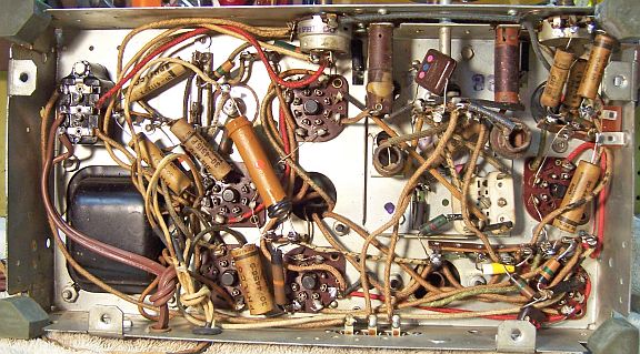
Restoration Results
Chassis Before Restoration
|
 |
Chassis After Restoration
|
 |