A rare 240 volt DC model designed for export markets
My antique radio restoration logs
There were two cabinet styles for the Philco Model 46: a cathedral similar to the Philco Model 20, and a Highboy console. My set is the highboy model. The Philco model 46 works on 110-120 volts DC, which allowed it to be powered from railway DC lines in Manhattan, for example. The model 46E was designed for export markets, and works on 210-240 volts DC. I have a British radio in my collection which also requires "DC Mains" at 240 volts, so perhaps these sets were designed for that market.
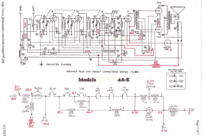
The circuit of the model 46 and 46E is very similar to the Philco Model 20. It is a 6-tube (plus ballast tube) TRF circuit, broadcast band only. However, the tubes used are quite unique and are rare. It uses 3 type 14 tubes, a type 17, two 71A's and a type 2 or 3 ballast tube (the Model 46 uses a type 2, and the Model 46E uses a type 3). The type 14 tube is a type 24A tube with a 14 volt 300ma filament instead of 2.5 volts. The type 17 is a type 27 again with a 14 volt 300ma filament. I was told that the types 14 and 17 were made specifically for the Model 46, and no other radio used them! Thus, they are quite rare and hard to find.
The radio was in very good condition as found. All the metal shields were present - which is unusual. The chassis was very clean - no rust! All chassis labels were intact. One type 14 tube had been replaced with a type 36 tube, which would probably have worked but has a 6.3 volt 300ma filament, so the resulting filament string voltage would have been higher than normal. I was fortunately able to acquire a replacement type 14 tube from George Fathauer (who is no longer supplying antique radio tubes - the business sold to Vacuum Tubes, Inc. of Orlando, Florida.) I tested the extant type 14's and 17's using tube tester settings for a type 24A and 27, but set the filament voltage to 12.6 volts (I know of no tube testers that will actually test a type 14 or 17). The two 14's tested good even at 12.6 volts, but the 17 tested weak (perhaps due to the lower filament voltage).
The schematic in Riders and in the Philco service bulletins (available at Philcoradio.com) are not correct for the Model 46E. Both sources state that the only differences between the Model 46 and 46E are some component values and a different ballast tube. That is not the case - the 46E is very different from the model 46. I have marked up a schematic of my model 46E as found below. The markings in RED indicate the differences. The biggest difference in the 46 and 46E is the wiring of the filament string. I separately documented the filament wiring in my model 46E along with the voltages present. The model 46E takes advantage of the higher B+ voltage available on the model 46E. The position of the 71A's in the filament string determines their bias. Note also that various B+ voltages are derived from taps along the filament string!
Other problems with my set as found were:
Fortunately, major components such as the large wire wound resistors, volume control and chokes were good, as was the output transformer and speaker field. If any of these had been bad, the restoration would have been much more difficult.
I start all repairs and restorations by checking all components up front. I then make a survey of all repairs and parts needed. Next I took a high resolution photo of the chassis underside in order to check my work and also to reproduce component mounting and lead dress (critical in some radios). All the capacitors (except micas) in the Model 46E are either Philco bakelite block types, or are in metal cans. All capacitors were removed and rebuilt in their original cases to preserve the original appearance. Any defective or out of tolerance resistors were replaced with original types (dog bone types) that were checked for value. Wire wound resistor 39 was successfully repaired. The primary windings of RF transformers 8 and 13 were rewound. They only had about 50 turns of wire, and the winding was on the outside of the transformers. I used magnet wire of a similar gauge as the original, and was careful to match the position of the coil and the winding direction.
The driver transformer (part 26) was the most serious challenge. One of the dual independent secondaries was open. Fortunately, the primary and one secondary were OK, so I was able to measure the ratio of the transformer by driving the primary winding from my HP 200A audio oscillator (capable of up to about 20 volts at pretty good power!) at 500 hz and measuring the primary and secondary voltages. I found that the ratio was 1:2 primary to each secondary. Luckily, the Hammond T124E had those exact specifications and was rated at 5 watts. It even had the same mounting centers as the original transformer!
The pilot lamp was missing, so its type was not known. After restoration, I replaced it with a #40 and brought up the power and monitored the voltage across the lamp. Turns out that a #40 was the correct lamp.
The large capacitor pack 34 was rebuilt. The original was 0.13, 1.0, 1.0, and 3.5 mfd. I could not use an electrolytic type for the 3.5mfd capacitor, since there is really nothing to prevent the line cord from being plugged in backwards, which would have ruined an electrolytic. So I used 0.15mfd and 1.0mfd 630 volt capacitors for the 0.13 and 1.0mfd caps, and a 1.0 and 2.25mfd 630 volt caps in parallel for the 3.5mfd cap.
The tuning capacitor mounting bushings were shot. Replacement were fabricated from gum rubber washers sold by Radio Daze and AES, super glued to rubber grommets cut in half.
The chassis and all shields were cleaned using GoJo hand cleaner and 00 steel wool after most parts were removed for cleaning or rebuilding. The power switch was defective, but responded to a good cleaning using "Big Bath" spray cleaner through holes in the laminations and repeated operation. Globe type 71A tubes were installed for appearance.
A kludge power source was lashed together using an isolation transformer, a variac, a 120-240 volt step-up autotransformer, 4 1N4007 diodes in a bridge configuration, and a 500mfd 450 volt filter capacitor. The radio requires 210-240 volts at about 325ma.
The restored radio was connected to the supply and the voltage slowly increased while carefully monitoring the filament voltages and brightness of the tubes. The radio worked well on the first attempt! All the B+ and bias voltages were found to be correct. The set was then aligned. The performance was found to be similar to the Philco model 20.
The radio is very impressive when operating, since the Type 3 ballast is illuminated much like a light bulb! It dissipates 37 watts!

The highboy cabinet was in good condition. There was a slight amount of damage in shipping, and this was repaired. The grille cloth was replaced using reproduction cloth from grillecloth.com, the type used for the Philco 70 and 90 (pattern #1, Whiskey). Some loose joints were re-glued and clamped. The entire cabinet was cleaned using GoJo hand cleaner and 00 steel wool. Nothing else was done to the cabinet.
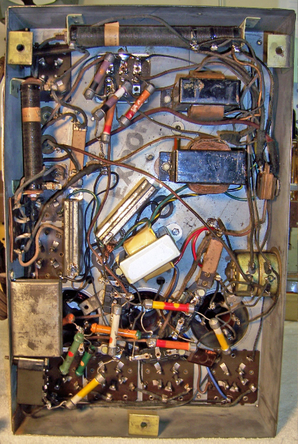
One of my main objectives in this restoration was to ensure that any repairs were not obvious. Unfortunately, the transformer 26 and some bad wiring that was replaced are visible. The 99K resistor in the center of the chassis near the driver transformer 26 is not original and was removed (a lame attempt by a serviceman to work around the open driver transformer secondary). Here is the chassis as found and after restoration:
|
Chassis Before Restoration |
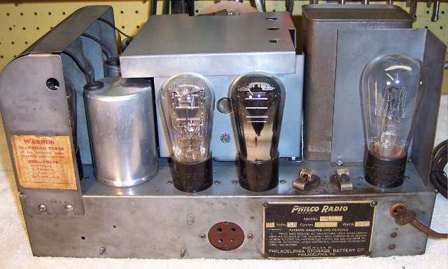
Chassis After Restoration |
 |
 |
Below: Front View of Restored Chassis

Below: Back View of Restored Chassis
Below: Side View of restored Chassis
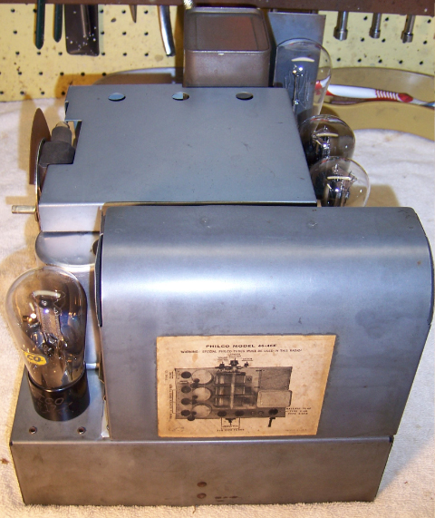
Below: Side View of Restored Chassis

Below: Completed Radio
