Philco 58C "Pee-Wee" Restoration
 |
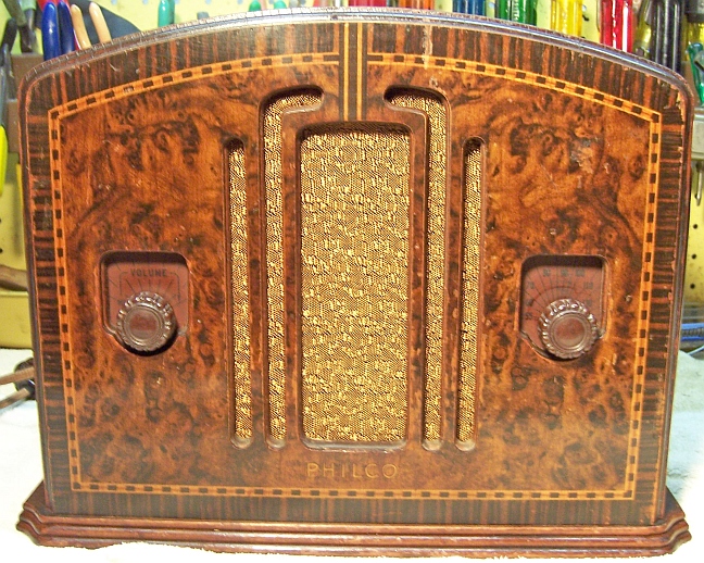
The Philco 58C from circa 1933/34 is a compact four tube superhet
circuit radio often called the "Pee-Wee" or cigar box
radio. The cabinet front has a "photo finish"
(picture of wood!) making it appear to consist of burl veneer and inlays.
The schematic and a parts list for the radio can be found on Nostalgia
Air under Philco model 57. The model 58C uses the same circuit as the
model 57 except for an added pilot lamp. Any part number references in the text below reference
the model 57 schematic. |
My
antique radio restoration logs
Overview
The radio was purchased on eBay. This is the second example
of this radio I have restored. Externally it appeared to be all
original, complete and in good condition. It was described as not working,
for parts or restoration. The power cord had been cut off.
The circuit is quite unusual: it uses a type 77 tube as combined
detector/oscillator. There is no IF amplifier stage. A second type
77 tube acts as a regenerative grid leak type second detector. The
regeneration adds considerable gain to the stage (and yes, it will squeal if not
adjusted correctly). The chassis is quite compact, and servicing is difficult.
Access to some components requires partial disassembly.
The radio receives the standard broadcast band plus the old police call band -
there is no dial scale for this band. According to RadioMuseum.org, the range of
the police band is 75-200 meters (1.5-4mHz). There was NO indication
of a model number found anywhere on the radio chassis or cabinet. Philco used
several variations of this 4-tube chassis in four different cabinets!
Previous Servicing
I always attempt to avoid purchasing radios that have been
"restored" by collectors or flippers, and am looking for either all
original examples or those which have been "lightly serviced" in the
distant past by radio service shops. Except possibly for tubes, this radio
appeared to be all original and untouched:
-
All resistors were original.
-
All capacitors were original. All were either
Philco bakelite block types or mica capacitors.
-
The
original filter capacitor, along with its cardboard cover, remained in
place.
-
The power cord had been cut off near the chassis exit.
-
Several tubes likely had been replaced. The
originals would have been branded Philco. There were two Philco tubes
installed: one with a date code M4 (which may have been original - 1934?)
and one with a date code P9 (likely a replacement)
-
There was no sign of any solder joints having been disturbed.
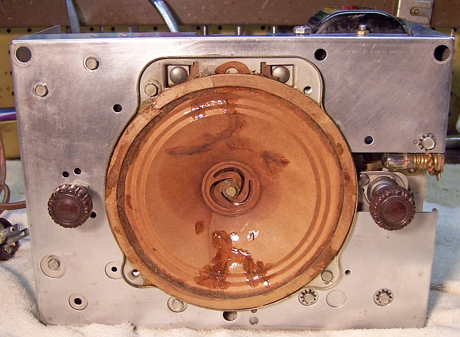
Cleaning
Before cleaning, the speaker, band switch, filter
capacitor, tuning capacitor, and the two bakelite block capacitors on the back
of the front panel (parts 10 and 26) were removed. I feared that the air
compressor might damage the very fragile speaker cone. Removal of the tuning
capacitor was VERY difficult since the retaining screws were hidden BENEATH two transformer shields (for
parts 2
and 13). Several parts had to be disconnected from the transformers, the
two retaining screws removed, and the two transformer shields moved out of the way in
order to remove the three screws and star washers holding the tuning capacitor in place.
The dust was then blown off
the chassis with an air compressor. The
chassis top and sides were cleaned using GoJo (white) hand cleaner and 000 steel wool. The
chassis was then carefully vacuumed, and any remaining steel wool fragments
removed using a magnetized screwdriver and masking tape.
Survey
Before starting repairs I tested all the parts that I could, in
case there were any showstoppers.
-
The power transformer was OK. The AC voltage on both sides of the high voltage center tap was
balanced with 20 volts applied to the primary through a Variac. Power consumption at full line voltage with no load was less than 10 watts, which
indicated that there were no shorted turns. I always perform this test
prior to restoration, even on working radios, since transformer overheating due to shorted turns or
other problems may not be obvious with only brief testing. Many
collectors new to restoration often completely recap a radio, and even
replace resistors and tubes, only to find out they have a bad power
transformer after completion.
-
The primary winding of the antenna coil (part 2) was open.
The tuned secondary was OK.
-
The oscillator coil and IF transformer were OK.
-
Four dogbone
resistors were out of tolerance (more than +/- 20%).
-
The pilot light was OK.
-
The speaker field and output transformer were OK.
-
The grille cloth was torn, and there were tears in the
speaker cone.
-
The power switch on the volume control was intermittent.
-
The volume control was bad - operation was erratic.
Restoration Strategy
Since all of the original parts were still in place I decided to try
to maintain the
original chassis appearance to the extent possible yet restore operation. All
original capacitors would be rebuilt in their original cases (restuffed),
including the original
filter capacitor. Any out of tolerance
resistors would be replaced with the same types if available. When I replace a component, I
always remove the original part completely from a terminal. Other good components connected at the terminal are protected from heat using old medical
clamps (hemostats). Excess solder is then removed using a solder sucker in order to
expose terminal holes for reattachment of the rebuilt or replaced component.
I assume that all paper and electrolytic capacitors are leaky and thus should be
replaced (I always "restuff" the original components if possible). I
do not replace mica capacitors, but may test them in place if possible (usually
this requires disconnecting one end of the capacitor).
Repairs
Antenna Coil
The primary winding of the antenna coil (2) was open. In order
to remove the coil for repair, the band switch (8) and associated mica capacitor
(5) was disconnected and removed. All connecting leads were then removed from
the coil. The coil was held in its shield can by a single hex screw and star
washer on the terminal end. It was NOT easy to remove this screw due to access restrictions. I
used a small open end wrench (1/4") to remove it. The coil was then
manipulated from its shield can (not easy). It would have been easier to
disconnect both the antenna coil and oscillator coil connections and then remove
both coils and their shields as a unit. But I did not want to risk damage to the
coils or disturb lead dress if not needed.
Fortunately, the open winding was on the outside. Also, it was
not the tuned winding and thus not critical as to number of turns or wire size.
The coil was wound on a plastic insulator on top of the secondary winding. It
was covered by wax. As much of the wax was removed as possible using a heat gun.
The top end of the coil was unsoldered from its lug. That end passed over
the top of the coil. I then attempted to unwind the coil so that the number of turns
could be counted. I noted the number of turns, which end went to which terminal,
and the winding direction. Since there were several breaks (due to corrosion),
my count was only approximate. I counted 22 turns. I rewound the coil using
single cotton covered magnet wire which was similar to the original. I then
secured the winding in place using melted rosin (salvaged from servicing RCA
Radiola Superhet catacombs!)

Volume Control and Switch
The original volume control was bad. Its resistance initially
measured 43.5K (specification is 20K ohms). The resistance jumped around as the
control was rotated. I tried using some cleaner (GC Big Bath spray) but this made
things worse! The resistance jumped to 200K! The resistance element in this
type of control (C. T. S. Type T) is a thin layer of carbon deposited on a
cardboard or fiber substrate. Any attempt to clean it will result in
removal of the thin carbon layer. So I had to find a replacement. I
keep a stock of new (IRC type D and Q) and used controls of various types. Some
of the parameters required are critical in this application:
-
Must have an attached switch
-
Since there is a metal shield behind the control, the
distance from the panel to the shield (and thus the depth of the control
plus its switch) is limited.
-
The control varies the radio volume by shunting the antenna
coil primary winding. So typically a special taper is used in order to
obtain smooth control over the entire range of rotation. One type sometimes
used is called a "reverse log taper". The change in resistance from
minimum volume is fast at first, then decreases as maximum volume is
approached. This is just the
opposite to the taper typically used for volume controls in modern
receivers. The normal alternative is to use a linear taper control.
But this results in smooth control over a very small range of rotation.
-
Must accept a Philco push-on knob, which fits on a round
shaft with a shallow flat portion.
I found a similar older type control in my stock that measured
about 40K. After cleaning, operation was smooth. The control had an attached
switch, which was needed. The shaft length was similar to the original, but was
round and not slotted for a Philco push-on knob. The overall depth was
acceptable, and there was plenty of clearance between the switch lugs and the
metal shield. But the taper of the control was unknown. Although the low
resistance hinted that this control may have been used in a similar
circuit. This would have to await testing.
Resistors
The radio used older style "dogbone" type
resistors. One was an original cast metal end type and the others were wound
end types (lead wires wrapped around the ends of the carbon rod element and then the wraps soldered
together).
I keep a stock of NOS and used "dogbone" resistors and buy all I can
on eBay and at radio swap meets (when reasonably priced)! Of course, most of these resistors, even NOS resistors, have also
drifted in value and no longer have their marked values. My solution is to
find a replacement resistor of the correct value and size as measured (ignoring the
markings), and then repaint it to the needed value codes using enamel hobby
paint! I was able to find suitable replacements for three of the four
resistors - all 1/2 watt type. In one case I was forced to use a smaller
1/3 watt size dogbone to
replace the original 1/2 watt original (part 24). The replacements were repainted using
hobby enamel paint to the color codes of the original resistors.
Paper Capacitors
All paper capacitors were Philco bakelite block types. All were removed from the radio
(one or two at a time, making careful notes of connections),
their contents removed, cases cleaned using lacquer thinner, and restuffed using modern
630 volt film
capacitors. Before removing the contents I unsolder the internal capacitor
leads from the outside terminals and
clean off the terminals. I use mechanical methods of removing the bulk of the
potting tar and capacitors (small screwdrivers). One must be careful NOT to pry against
the bakelite case, as it is easily broken. Some collectors use heat to
remove the contents.
Filter Capacitor
The original filter capacitor was still in place, along with its cardboard
cover which simply slips off. The original capacitor was a screw based dual dry electrolytic
rated at 8 and 4 mfd at 450 volts (it was marked 12mfd). The terminal lugs were
color coded: Black (common negative), Red (8mfd), and Blue (or green) 4mfd. But
the wiring of my all original radio did not match the schematics in
Riders/Nostalgia Air or the schematics available at Philcoradio.com. These
schematics show that the input filter capacitor (connected to the rectifier
filament) is 4mfd. In my radio, the input filter was 8mfd (red lug). This
could have been an error in the schematic, an assembly error, or a production
change. I asked this question on the Philco
Phorums, but received no answer. I restored the radio as wired vs. the
schematic. It was restuffed with a 10mfd and a 4.7mfd
450 volt electrolytic. There was
plenty of room inside the case for these capacitors. The restuffing process for
this capacitor was as follows:
- The capacitor was mounted in my small Unimat lathe held in the 3-jaw chuck
by its mounting nut, and secured in place on the opposite end with the live
center. It was then deeply scored about 1"
above the base (almost through the case). I finished the cut with a fine tooth hobby razor
saw.
- The original contents were removed from the case by pulling. There
was no cement or tar holding the contents inside the case - only wax. Heat from a
heat gun allowed easy removal of the contents (quite messy!). Additional
heat added removed most of the remaining wax inside the can.
- The foil connections to the base terminals were cut using a sharp Exacto
knife with #11 blade. The paper insulation was also removed
from around the terminal lugs.
- The inside of the case and the base were cleaned using lacquer thinner
followed by soap, water, and a
toothbrush. They were then dried using a heat gun.
- The rivets that originally attached the terminal lugs to the aluminum
capacitor leads were ground off using a Dremel tool and grinding stone.
Removing the rivets left holes where the replacement capacitors could be
attached.
- The positive leads of each replacement capacitor were soldered to the red
(10mfd) and green (4.7mfd) terminal
lugs. The leads were insulated using spaghetti tubing.
- The negative lead of the replacement capacitors were connected to a common
negative #22 bus wire. This lead was insulated using spaghetti tubing and connected to the black terminal lug.
- The two halves of the case were then reattached using 3/4" PVC plumbing
couplings and epoxy. I added a few layers of masking tape
around the PVC coupling to take up any excess space.
Tuning Capacitor
The three screws retaining the tuning capacitor are under the antenna and
oscillator coil shield cans! The antenna coil already had been removed for
repairs. The two hex screws retaining the two coil shields were removed. By
disconnecting an 8K resistor (part 8) and mica capacitor from the oscillator coil, the
shields could be moved out of the way and the screws retaining the tuning
capacitor removed without disconnecting or disturbing other wiring to the
oscillator coil.
After removal from the chassis, the tuning capacitor was cleaned in my old
Heathkit ultrasonic cleaner using dilute ammonia. Since the entire unit could
not be cleaned all at once, several cleaning steps were done, with the capacitor
at various angles. After this cleaning and rinsing, the capacitor was cleaned using soap,
water, and old toothbrushes. It was then dried using a heat gun. Prior to cleaning
the capacitor, the vernier drive assembly was removed for cleaning and
lubrication. In addition, the trimmer capacitor screws, washers, and mica
insulators were removed. In order to retain the approximate original position
of the trimmers, the following procedure was used:
- The trimmer was fully tightened while noting the number of 1/2 turns (and
fractions) from the original position to fully tight.
- The trimmer screws, washers, and the mica insulator sheets were then
removed.
- After cleaning and drying, the hardware was reattached.
- Each trimmer screw was then returned to the fully tight position.
- Each screw was then backed out the number of 1/2 turns and fractions noted
originally.
The vernier drive assembly and tuning capacitor ball bearings were lubricated using automotive distributor cam
lubricant (grease).
Reassembly
The order of reassembly is critical. After cleaning the chassis and
tuning capacitor, the two shielded RF transformers under the chassis were still
loose and moveable. The parts were reattached in the following order:
- Volume control.
- Two bakelite block capacitors behind the front panel (10 and 26)
- Tuning capacitor
- Speaker
- The heat shield in front of parts 10 and 26.
- Antenna and oscillator coil shield cans.
- Filter capacitor. Access to the retaining nut is VERY LIMITED and a wrench
cannot be used. Once the nut was started on the filter capacitor
threaded base, the capacitor was rotated until seated. A couple of attempts
were needed in order that the three color coded capacitor terminals were in
their original positions when the capacitor was tightened. The capacitor
does not have to be extremely tight, since the common ground does not depend
on contact with the chassis.
- Band switch and associated mica capacitor.
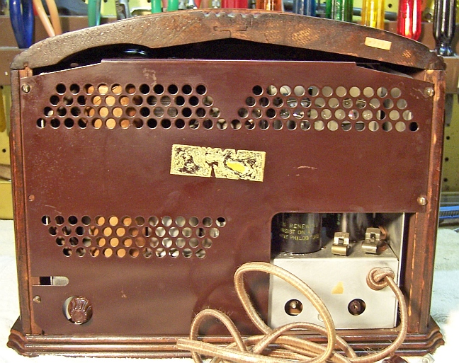
Other Repairs
The power cord was replaced by modern reproduction cloth covered wire, and an
old style acorn type plug installed. This type of cord is sold for
restoration of antique lamps.
The damage to the speaker cone was repaired using GC Service Cement.
Each tear or split was bridged using several layers of cement. Each layer was
allowed to dry before adding another layer (gently blowing on the cement speeds
up the hardening process).
The speaker grille cloth was replaced using a modern reproduction cloth
similar to the original.
All of the original tubes were reused, even though several were slightly
weak.
Cabinet
The cabinet was in very good shape but with some significant scratches and
dings. It was cleaned with GoJo hand cleaner and 00 steel wool.
Testing
After the radio was completely reassembled, power was applied through a fused Variac. Power was brought up slowly while monitoring
the B+ voltage. The radio came alive and worked on both bands- no assembly errors! The radio was then
aligned. Reception on the broadcast band was strong, especially for a 4 tube
radio! All I could find on the so called "police" band was weak
images of the same stations on the broadcast band and a few strong short wave
stations. The design appears to use the second harmonic of the local
oscillator for the Police band (the local oscillator frequency range is NOT
affected by the band switch). There was noticeable distortion and some speaker cone rattle
at higher volume levels, perhaps due the basic design of the radio and damage to
the speaker cone.
The replacement volume control worked very well. The range of control was
spread out quite well over the range of rotation, and not crowded onto one
end. I cut the required flat on the shaft using my Dremel tool.
Restoration Results
Most of my restoration objectives were met, but not all. There was no
intention of restoring the set to factory new appearance! My objective is
usually make the radio appear to have never
been repaired. Here are some of my
"misses":
- One replacement dogbone resistor (part 24) was not the same size as the
original.
- The replacement volume control was similar to the original, but not the
same. The control is actually not visible, since it is covered by a
metal shield.
- The replacement power cord was not exactly the same as the original.
- The speaker grille cloth was not the same as the original.
Chassis Before and After Restoration
Before
|
 |
After
|
 |