Philco Model 66 Restoration
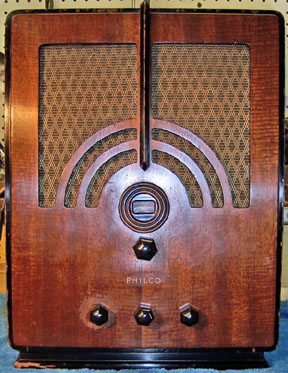 |
The Philco Model 66 is a 5-tube AC superhet circuit radio.
It receives the standard broadcast band and one short wave band. The
circuit is conventional, but the cabinet design is bold and quite deco! The radio had seen
minimal servicing in the past and had not been hacked excessively. This being the case, I
decided to try and retain the original top and bottom chassis appearance if
possible.
Previous servicing included several replacement tubes (I assume all
original tubes would have been Philco branded), a replacement volume
control (of the incorrect resistance), a tacked in electrolytic capacitor,
and one tubular capacitor (part 27).
The schematic for the Philco 66 can be found on Nostalgia
Air. Any part numbers will refer to numbers on that schematic. |
My
antique radio restoration logs
Survey
My usual restoration procedure is to first make a complete
survey of the condition of all components. The survey results guide my
restoration strategy. If major and unique components are defective and
cannot be restored, I may elect to sell the radio rather than restore it.
I assume that all paper and electrolytic capacitors are leaky and thus should be
replaced (I always "restuff" the original containers if possible).
-
There was one tacked in filter across the input filter (part
50).
-
Capacitor 27 had been replaced.
-
The volume control (part 39) had been replaced by a 20K
pot! I don't think the radio would have worked very well - the correct
resistance was 350K.
-
The AC switch was bad - open..
-
The AC line cord was original but had several bad places -
it was very stiff in spots.
-
Two tubes were bad - 80 (intermittent filament) and 75 (very
weak).
-
The rubber grommets supporting the tuning capacitor were stiff and had shrunk -
there was too much play.
-
The chassis washers were stiff and had shrunk. All
chassis bolts and washers were present.
-
All coils, transformers, and the filter choke were OK.
-
The speaker field and cone were OK.
-
Nine resistors were out of tolerance by 36% to 95% (dogbone types).
-
The wire wound resistor 44 was fortunately good - bias
resistor.
Repairs
Here's a hint for anyone restoring this radio. Many components are
mounted on a terminal board. this board must be removed in order to
properly replace components. It also blocks access to wiring and some
components below it. So my suggestion is to carefully tag all wires, take
good notes, and remove the terminal board first thing!
All paper and bakelite block capacitors were rebuilt in their original cases
using modern 630 volt film capacitors in order to maintain the original
under-chassis appearance. One non-original capacitor (part 27) was
replaced by a Philco tubular capacitor that was restuffed (unfortunately I did
not have an original Philco capacitor of the correct value - .1uf).
The two can type electrolytic capacitors were also rebuilt in their original
containers. The cans were scored on a Unimat lathe and the cut completed
using a hobby razor saw. The cuts were near the base in both cases so that
the joint would be hidden by the clamps or insulating cover. The original
contents were removed, the cases cleaned, new 450 volt electrolytics installed
inside, and the two halves of the cans joined using PVC plumbing couplings and
epoxy. The single capacitor (part 49) was originally 6uf at 475
volts. The dual capacitor (part 50) was 2 x 8uf at 450 volts. I used
10uf at 450 volts for all of them.
All original resistors more than 20% out of tolerance were replaced. I
used dogbone type resistors as were used originally. I picked out NOS and
used dogbone resistors that had the correct resistance and then repainted them
to match the original resistor's color codes. The replacements had also
drifted in value, and may continue to drift, as would most new carbon
composition type resistors. But to me, maintaining the original look is
more important than long term reliability of the radio.
The capacitors inside the tone switch were replaced, and the switch filled
with rosin (the original was filled with tar).
Volume Control
The original AC switch on the volume control was bad. However the
volume control had been replaced by a 20K pot with switch. I was fortunate
to find an original Philco volume control in my junk box that was good.
The original control in the radio was Philco part 33-5006. I replaced it
with a Philco part 33-5306-2. It had the same resistance as the original
as well as the same shaft length and appearance! A real lucky find!
The only problem was that the flat on the shaft was too deep for the original
knob (meant for a different type of knob). This was fixed using a
cardboard shim in the knob.
Other Repairs
- The original line cord had several places where it had broken, and was
stiff in spots. I was able to cut it at a couple of breaks and splice
it back together (using shrink tubing to cover the splice). I was able to
salvage about 4 feet of the original cord, as well as the original plug.
- The tuning capacitor grommets were replaced. This eliminated
the play in the tuning capacitor. These grommets are available from Renovated
Radios, part GLg-Tuner.
- The chassis was cleaned using GoJo and steel wool, tooth brushes, small
bottle brushes, and pipe cleaners.
- The bandswitch was cleaned using lacquer thinner and Big Bath spray cleaner.
Testing and Alignment
Once the radio was reassembled and tubes installed, power was brought up
slowly using a variac. AC power was monitored using a watt meter, and a
DVM monitored the B+. The radio came alive immediately and worked.
Once at full power, voltage measurements were taken.
The set was aligned - no surprises. One of the IF trimmers was way off
- the rest were close. The oscillator, RF, and low-frequency padder peaked
up nicely.
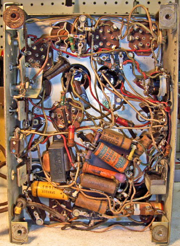
Restoration Results
|
Chassis Before Restoration |
Chassis After Restoration |
 |
 |
