Philco 90B Cathedral Restoration
 |
The Philco 90B Cathedral is a large 9-tube AC Superhet
circuit radio that receives only the broadcast band. This example
was the single 47 output tube version. The radio had seen a
moderate amount of servicing in the past. Six wax-paper capacitors
had been installed to replace likely leaky or open Philco bakelite block
capacitors. The copper Mershon filter capacitors had also been
replaced. But it appeared, at least initially, that all repairs were
reversible. That being the case, I decided to try to maintain the
original top and bottom chassis appearance and to reverse any previous
repairs to the extent possible.
The schematic for the Philco 90 can be found on Nostalgia
Air. Any part numbers will refer to numbers on that schematic.
The schematic
at Philcoradio.com is annotated with parts values in addition to part
numbers, and is indispensable. |
My
antique radio restoration logs
Overview
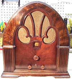
This radio was purchased on eBay at a reasonable price (these
models go for big bucks, especially if refinished or have excellent original
finish
cabinets). My example cabinet was presentable, with no damage or serious
scratches or dings, but the finish was heavily oxidized, and very
dark. It had its original knobs and grille cloth, and the cloth was in good
condition. The power cord was original, but frayed in places. All
tube shields were in place. When the radio was removed from the cabinet, it
appeared that mice had been living inside! There were lots of seeds and
some nuts present. But I saw no evidence of component damage or excessive corrosion due to
their urine. After cabinet cleaning, I did discover where small nails had
been used to secure the arch brace and the cabinet base. These were
hardly visible and were left in place, since attempting to remove them would
likely result in more damage to the finish. The eBay seller did an
excellent job at packing (triple boxed!) and there was no shipping damage. Here
is what the radio looked like as received:
Previous Repairs
The radio had seen a moderate amount of repair in the past, and
all repairs were far in the past, judging from the components used. This
was a well loved radio that someone paid a lot to have repaired, and several
times. Six wax-paper capacitors had been installed to replace the usually
leaky Philco bakelite block capacitors. In three cases, the replacement
capacitors had been installed in parallel with the existing capacitors, which
had not been disconnected (perhaps they had failed open?) In the other three
cases, wiring and other components had been disconnected from the bakelite
blocks and left hanging in space. In one case, one of the lugs of a
bakelite block capacitor had been cut short. But NONE of the original
bakelite blocks had been removed, fortunately. Once restoration started,
and the bakelite block capacitors were removed for restuffing, I found that in
3-4 cases a terminal had been cut and then soldered back to the stub left on the
capacitor! I assume this was done by the service tech to test the
capacitor. This was not obvious until the solder on the terminal was
melted in order to remove a component or wire.
-
The two copper Mershon filter capacitors had been removed
and replaced by tubular capacitors under the chassis. There were signs
of leakage and corrosion on top of the chassis where the originals had been
mounted.
-
The metal cased bypass capacitor blocks were all still in
place.
-
There were four original Philco globe type tubes still in
place, with 1931 (1B) dates codes. The remainder of the tubes were
replacements.
-
All of the original resistors were still in place.
-
The AC plug had been replaced. The cord itself was
original.
-
At least two bakelite block capacitors had been
replaced more than once - parts 23 and 28! It appeared that the
first repair consisted of cutting the lugs from the block capacitor,
installing a NEW bakelite block capacitor, and soldering the cut lugs
to the replacement capacitor lugs. The second repair left the replacement
bakelite block capacitors in place. The cut lugs from the first repair were
unsoldered from the lugs of the first replacement block capacitor.
This time tubular capacitors were substituted - parts were left hanging in
mid air. As a result, most of the time I had an original bakelite
block capacitor left that could be restuffed and the original component
placement restored.
-
There was paraffin wax inside the base of the tuning
capacitor as well as underneath it. Some had leaked under the chassis
as well. I cannot imagine why this was done, unless it was an attempt
to keep the tuning capacitor from flopping around due to failed mounting
grommets!
Survey
My usual restoration procedure is to first make a complete
survey of the condition of all components. The survey results guide my
restoration strategy. If major and unique components are defective or
missing and
cannot be restored or replaced, I may elect to sell the radio rather than restore it.
I always assume that all paper and electrolytic capacitors are leaky and thus should be
replaced (I always "restuff" the original containers if possible).
Any mica capacitors are assumed OK until testing proves otherwise. I
never apply power to an unrestored radio, even through a variac or "dim
bulb" tester.
-
Seven resistors were out of tolerance (more than +/-20%). All were dogbone
type resistors of various wattages. Some were the older cast-end type
dogbone resistors.
-
The speaker cone, field coil, and output transformer were
OK.
-
The power transformer was OK. The high voltage was
balanced across the center tap with 20 volts applied through a variac.
With full power applied (no tubes present), the wattage consumed was less
than 10 watts. A transformer with shorted turns will draw excessive
power and will heat up. I use a real analog watt meter for these
tests.
-
The filter choke was OK.
-
The large wire wound resistor 58 was fortunately good and in
tolerance.
-
All RF coils and transformers were OK.
-
The IF transformers were OK.
-
All tubes were good except for one: an original Philco type
24 (globe) tube with a 1B (1931?) date code. It tested good, but also
indicated an intermittent short. I would hesitate to use it,
unfortunately. The three other original Philco tubes were good!
-
The chassis washers were deteriorated, which is common.
-
The tuning capacitor mounting grommets had hardened and
shrunk, allowing the capacitor to move around.
-
The cabinet feet were still OK.
-
All wiring was cloth covered and was OK with the exception
of one metal capacitor lead, which was frayed. The speaker cable also
had some breaks, but it is not easily replaced since the plug is riveted
together! It was left as is.
-
All tube shields were present.
-
The pilot lamp was burned out
Repairs
The chassis was very dirty, and had seen mouse activity - two holes in the
chassis top left when the filter capacitors had been removed provided perfect
access! No nest was found. All tubes and shields were removed and dust was removed using an air compressor.
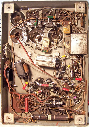
Before starting repairs, I took photos of the chassis
top and bottom so that routing of wiring and component placement could be restored.
Lead dress is often critical in radios. The tuning capacitor was
removed for cleaning, for replacement of the mounting grommets, and to remove
the paraffin wax underneath.
I then removed all
of the non-original capacitors, documenting their locations
and connections. In the process, I documented using a sketch where all the original
components (resistors) were likely connected (to terminals on the bakelite block capacitors) When I replace a component, I
always remove the original part completely from a terminal. Other
components such as mica capacitors and in-tolerance resistors connected at the terminal are protected from heat using old medical
clamps (hemostats). Excess solder is then removed using a solder sucker in order to
expose terminal holes for reattachment of the rebuilt or replaced component.
The top and sides of the chassis were cleaned with GoJo hand cleaner and 00 steel
wool. Since this process may leave metal residue, I then went over the
chassis with a vacuum cleaner followed up by a small magnet and masking tape. The tuning capacitor was
disassembled and its parts cleaned using soap, water, and old toothbrushes. Some
parts (or portions of parts) were also cleaned in my old Heathkit ultrasonic
cleaner using dilute ammonia. After drying, the
bearing surfaces were lubed with automotive distributor cam lubricant. The tuning capacitor grommets were replaced by
GLg-Tuner grommets from Renovated
Radio, thick side up. These worked OK, but the center hole was
slightly large and allowed some movement of the capacitor.
Capacitors
Bakelite Block Capacitors
All original Philco bakelite block capacitors were removed from the radio
(one or two at a time, making careful notes of connections),
their contents removed, cases cleaned using lacquer thinner, and restuffed using modern
630 volt film
capacitors. Before removing the contents I unsolder the internal capacitor
leads from the outside terminals and
clean off the terminals. I use mechanical methods of removing the bulk of the
potting tar and capacitors (small screwdrivers). One must be careful NOT to pry against
the bakelite case, as it is easily broken. Some collectors use heat to
remove the contents. Here is the restuffed capacitor 52 (the line bypass capacitor,
Philco part number 3793E), which contains two 0.015mfd capacitors:
Metal Cased Bypass Capacitor Blocks
The two metal cased bypass capacitors 24 and 30 were restuffed using new film
capacitors. The capacitor 24 had three identical capacitors inside, so
there was no need to identify the leads. I did measure the length of each
lead as it was disconnected, since at this point I did not know if all the leads
could be salvaged. Another reason to measure the lead length (they were
all different) is to maintain the original lead dress and routing. In the case of capacitor 30, it contained
three different
capacitors, and originally had three different color leads. Unfortunately,
the colors had faded or were very dirty and the colors could not be
identified. They were identified by where they connect in the schematic,
and were tagged using marking tags. Again each lead was measured as it was disconnected. The Riders schematic has no component values
marked, so the leads of this capacitor had to be identified by referring to the schematic
at Philcoradio.com
I was able to salvage all of the original lead wires and reuse them with one
exception (a frayed wire).
The original insulators inside were also retained and reused. These
capacitor types
are very easy to rebuild by straightening the metal tabs, removing the fiber top
cover, unsoldering the internal capacitor common lead from the case, freeing up the contents by passing a thin blade between the
insulator and metal case, and pulling out the contents. The tar covered
capacitor inside the insulator was discarded after removing the original lead wires for
reuse (scrape away enough tar to unsolder the lead from the capacitor body). Capacitor 24 was
originally three 0.25mfd capacitors. It was restuffed using three
0.22mfd/630 volt axial film capacitors. The original leads were soldered
to the shortened replacement capacitor leads, and insulating spaghetti tubing was applied
to prevent shorts. The three capacitors were then wound with a strips cut
from paper towels, which was secured with masking tape in order to fill up the space inside the
original can and original insulator. A common ground bus was soldered to
the side of the case where the original common ground was removed. The
original insulator is important since it supports the fiber board cover, which
has a hole for the three leads to emerge. Here is the restuffed capacitor
24:
 |
Capacitor 30 was constructed the same way, and it was
restuffed using the same method. It contained a 0.1mfd, a 0.25mfd
a 1mfd capacitor. It was restuffed using a 0.1mfd, a 0.22mfd and a
1mfd film capacitor all at 630 volts. I only
stock 630 volt film capacitors. Its original leads were also
reused. |
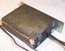
Mershon Copper Filter Capacitors
Both original Mershon copper filter capacitors (6mfd) were missing.
Fortunately I had several copper Mershon capacitors in stock, complete with
their mounting and terminal nuts. Since Mershon capacitors were so distinctive
in appearance, I purchase all I can find that are reasonably
priced on eBay or at radio swap meets. I had one 6mfd unit, one 4mfd unit
and two10mfd
units. The 10mfd units were much larger than the originals (these were
possibly used in the 25-40Hz versions of the Philco 90). The 4mfd
unit was about the same size as the 6mfd unit, and both were about the same size
as the original 6mfd units in my restored
Philco 70B. So I used the 4mfd and
6mfd Mershon capacitors for my Philco 90 restoration. An observer would have to have
very good eyes to tell the difference between the 4mfd and 6mfd units. I was missing the
insulating fiber mounting
bushing and negative terminal for the one capacitor that was insulated from the
chassis. I was also missing the correct positive terminal lugs for both
capacitors. I was able to obtain all of these parts from the friendly folk on
the Antique Radio Forums
Classified.
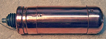
The replacement copper Mershon capacitors were
restuffed. Some collectors have been able to remove the tops of these capacitors in order
to restuff them. I have never been able to do this easily, and did not want to
risk damaging the very nice looking copper capacitors. Plus, with that method, the positive stud and electrode have to be removed as a unit (I wished
to retain the original positive stud). Before restuffing,
the cases were polished using Brasso metal polish. To restuff them, the
capacitors were chucked in my small Unimat lathe (gripped by their mounting nuts) and their cases
deeply scored about 1"
up from the bottom. The cuts were then completed using a hobby razor saw
and cleaned up using an Exacto knife with a sharp #11 blade. This leaves only a thin line on the
case - hardly visible. The original contents were then removed and the
inside of the capacitor case cleaned. The original positive electrode foil was removed and the
stud was cut short and then drilled to accept a ground lug and 4-40 screw and
nut. The positive lead of a replacement 10mfd/450volt capacitor was
attached to the ground lug. The negative lead of the new capacitor was
extended, insulated using spaghetti tubing, and routed though a
small hole drilled into the hard rubber base. This lead was attached to the original ground
lug (the insulated capacitor) or clamped between the capacitor base and the chassis. The two parts
of the case were then rejoined using 3/4" PVC plumbing couplings and epoxy.
I used a wrap of masking tape to ensure a snug fit inside the capacitor halves
before applying the epoxy (Devcon 5-Minute Epoxy). Here is one capacitor during assembly and
when completed:
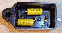
Tone Control
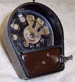 |
The tone control rotary switch contains three capacitors: a 0.015mfd and two
0.01mfd units. It was restuffed with new capacitors using the same
technique as used for the bakelite block
capacitors. The existing
capacitors, which were embedded in tar, were dug out mechanically.
The existing wiring to the switch contacts was removed, since the
rubber insulation would fall apart if moved. As much tar as possible was
then removed mechanically using various tools. The bakelite case
was then cleaned using lacquer thinner. The capacitors were
replaced using 630 volt film capacitors, and the wiring to the switch
contacts was replaced using bus wire and thin spaghetti tubing.
The control was then sealed using melted rosin (left over from servicing
RCA Radiola Superheterodyne catacombs) to hold the capacitors in place.
This wax melts at low temperatures
and will not damaged new components. Some collectors use tinted hot glue
or even caulk for resealing components. |
Resistors
Most resistors in the set were a mix of early cast-end dogbone type resistors
and later dogbone types having wire leads wound around their ends. Seven
resistors were out of tolerance by more than 20%. Five were early cast-end
type dogbones, and two were wound end type dogbones. I maintain stocks of NOS
and used dogbone resistors of both types, and buy all I can find that are
reasonably priced. I also NEVER throw away a used dogbone resistor, even
if out of tolerance. Searching my stocks, I found suitable replacements
for all seven (selected by measured value and size (wattage) rather than marked
value, since most resistors of this age will have drifted, even if NOS). In the
photo below, the 70K Philco cast-end resistor (top row, right) was in
tolerance, although its leads were short. The NOS 50K 1/2 watt wrapped end
resistor next to it was also in tolerance. The original resistor was much
shorter but was the same type. I found one other cast-end resistor in my
stock marked 70K that was close to 90K in value. It was repainted as a 99K
resistor using hobby paint (bottom row, right). Other wrapped end
resistors were found that were close to the remaining needed values. These
were also repainted to the needed values using hobby paint. The final result was
that three of the original cast-end dogbones were replaced by wrapped end
dogbones. This of course was a compromise, but reproducing cast-end resistors is beyond my skill level - some collectors do it - I have tried and
failed. I have seen other Philco model 90 sets where almost ALL of the
resistors were wrapped-end vs. cast-end types. So apparently there was a
transition from the earlier type to the later type.

The volume control worked smoothly, and its resistance looked reasonable (160K).
Its resistance is not documented in the Riders schematic, but is marked as 500K
on the Philco 90 schematic found on Philcoradio.com.
Other Repairs
The rotary power switch was removed from the radio and flooded with Big Bath
cleaner while rotated many times (there are openings in the body of the switch
where the cleaner can be applied). This failed to produce a reliable ON
condition as measured by my DVM. I next attempted to clean the switch in
my old Heathkit ultrasonic cleaner using dilute ammonia and water, followed by
drying using a heat gun. This also did not help. I repeated the Big
Bath cleaning step, and the switch worked about 90% of the time. I then
tested the switch using a 60 watt light bulb at full line voltage. It
seemed to work perfectly! I suppose it needed to switch some current to
work reliably. It was returned to the radio for testing after restoration.
I did have a suitable replacement in stock if later testing proved to be a
problem - a NOS rotary switch of the same type, but with a longer round shaft
and DPDT rather than single pole.
The power cord was original and somewhat stiff. If folded sharply, the
conductor insulation would break. There were two areas where this had
occurred, plus areas where the outer cloth covering was worn off. In order
to maintain as much originality as possible, the
cord was repaired using shrink tubing. An old style plug was installed.
The speaker cable had insulation breaks in places, but it was not
replaced. Replacement of the wiring would be difficult since the speaker
plug is riveted together! And of course, any replacement wiring would not
look anything like the originals.
Cabinet
The cabinet was vacuumed and then cleaned using GoJo (the white type, not pumice) hand
cleaner and 00 steel wool. This removed some of the dirt, but the dark
oxidized finish remained (mostly on the arch and sides). The cabinet was then waxed using
Johnson's paste
wax. The grille cloth was simply vacuumed. The chassis washers were
replaced using CW-5 washers from Renovated
Radios. These seemed to be close to the correct size, as the control shafts
were reasonably centered. The next thickness available was much too
thick. The small nails securing the base and arch brace were left in
place.
Testing and Alignment
Once the radio was reassembled and the tubes installed, power was brought up
slowly using a variac. A DVM monitored the B+. The radio came alive immediately and worked.
Globe tubes were installed in place of some of the newer ST types that came with the
radio. But I did not have enough good globe 24's or a good globe 47 to
convert the set to ALL globe tubes. I also did not replace one of the 27's
with a globe tube, since it was hidden inside a shield. The set was then
aligned. The alignment went well, except for the low frequency
adjustment. By rocking the dial and adjusting the low frequency padder, I
found the output was continuing to rise with the padder at maximum capacity
(fully tight). I did measure the parallel fixed mica capacitor (40), and
it was right on specification (as was the parallel resistor 41). I suppose
that the coils may have changed inductance over time, and with moisture
incursion.
The power switch worked reliably - I made a mental note not to rely on DVM
resistance measurements in the future! I suppose some switches (with dirty
or oxidized contacts) may need some current through them to work reliably.
The set had excellent sensitivity all across the dial, and its tone was
excellent. The B+ was slightly high - 267 volts vs. 250, likely due to
using 10mfd filter capacitors instead of the original 6mfd units. Like all
of my radios of this age, I operate the set using a fused bucking transformer at
111 volts (which was typical of 1931). Line voltage at my home is 122
volts (ouch!)
Restoration Results
Most of my restoration objectives were met, but not all. There was no
intention of restoring the set to factory new appearance! My objective is
usually to reverse any prior servicing and make the radio appear to have never
been repaired. I do not go so far as to artificially "age"
solder joints, as do some collectors! Nothing gives away a restoration
faster than bright and shiny solder joints. Here are some of my "misses":
- One Mershon copper filter capacitor was 4mfd rather than 6mfd (but almost
the same size).
- Three cast-end dogbone resistors were replaced using wound-end dogbone
resistors. Some of the original wrapped-end dogbone replacements were
larger than the originals, but the same type. This is not much of a
departure from originality, since I have seen other model 90 sets with
different mixes of cast-end and wrapped-end dogbones, and of different
physical sizes.
- The original line cord was repaired using shrink tubing. The plug
was an old style reproduction. The plug that came with the radio was
rubber and obviously not original. I have not clue what an original
plug might have looked like.
- One chassis bolt washer was not original (a fender washer, but rusty, so
it had been there awhile).
- The 47 tube, two 24 tubes, and one 27 tube were not globe types.
Only three of the tubes were original Philco with correct date codes.
I generally do not worry about trying to equip a set with all Philco branded
engraved base tubes with correct date codes! This would be almost
impossible to achieve with good tubes.
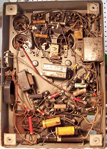
Before and After Restoration Photos
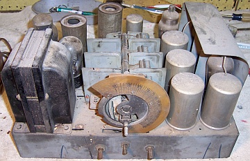
Chassis Before Restoration
|
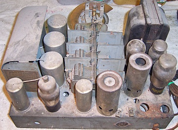
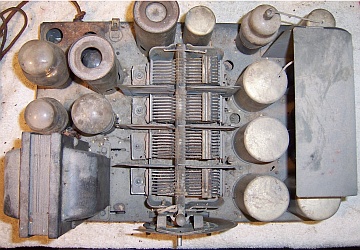
Chassis After Restoration
|
 |
 |


