My antique radio restoration logs
This set was purchased on eBay for a very reasonable price. But I did have a good 3KP1 (green phosphor scope tube) in stock, since most Pilot TV-37's arrive with dead 3KP4 CRTs. Usable 3KP4's are VERY hard to find, and expensive when you do find one. I fully expected this one to be dead, but to my surprise the filament was good! So there was at least some hope that the CRT would be usable.
The cabinet was in excellent condition with all parts present - cabinet feet, knobs, screws, even the knob felts were present. The bakelite bezel was not broken - another typical problem with these sets. When the cover was removed, the set appeared to be all original, even possibly the tubes (mostly Ken-Rad branded). The speaker output transformer had been changed, but all other parts appeared original. These was no cheater cord installed on the set (that may have saved it from being destroyed by plugging it in before it was resetored).
I had a set of SAMs photofacts available for this set from a previous restoration - Set 62, Folder 16. But there were lots of differences between my set and SAMs:
The filament string wiring totally different (the 3KP4 was first in the string in my set vs. in the middle in SAMs)
My set had no ballast. Instead it used several 1/2 watt carbon resistors in various places
The filter capacitor C2 was no longer mounted under the chassis. Instead a twist lock type was mounted where the ballast would normally be on top of the chassis.
There were some part value differences
Some 1500pf capacitors were installed in the vertical and horizontal sweep outputs and not shown in Sams
My usual restoration procedure is to first make a complete survey of the condition of all components. The survey results then guide my restoration strategy. If major and unique or unavailable components are defective and cannot be restored, I may elect to sell the item rather than restore it.
30 resistors were out of tolerance (20-50% high). Some could not be tested initially due to leaky capacitors. These were tested as the leaky capacitors were replaced.
There were no signs of overheating or burning
As found, the 3KP4 CRT filament was OK!
All tubes tested good+
All coils and transformers were OK
The AC cheater cord was missing
All wiring was in good condition
Two control pots had frozen shafts including the volume control - the shafts would not budge. I tried oil as well as penetrating oil - no luck.
This set is very easy to work on - almost as easy as a radio! It can be serviced upside down on the bench, and since it does not have a power transformer, it is very light.
In the original set, the 3KP4 CRT is subject to filament burn-out at initial power on. The filament is in series with two strings of 300ma tubes in parallel. Turn on surge often burns out the 3KP4. To help prevent future failures of the very rare CRT:
I powered up the set slowly using a variac and watt meter. It worked the first time. I used a digital TV converter box and a set of VHF rabbit ears for an antenna, since I do not have an outside antenna (and my other vintage sets do not like cable!) Once the centering and size adjustments were in the ball park, a picture was received. At first, the set would break into oscillation if the contrast control was advanced anywhere near the point where there was acceptable contrast. Then I remembered that I had removed a tube shield from V5, the second picture IF amplifier tube. It did not look original - the shield was simply soldered to a tube socket rivet. I removed it originally. On a hunch, I reinstalled it. THAT FIXED THE PROBLEM! The set no longer broke into oscillation, and now the contrast was acceptable.
The resulting picture was a least watchable. Just to make sure, I checked the high voltage. It was close to specs at 2450 volts, so I left it alone. Sound was OK, but buzz would occur if the contrast control was advanced too far. This set does not have AGC. The DTV converter could be overloading the set also. And there have been discussions on the various forums that DTV converters have problems with sound on vintage sets. I made no attempt to align the set, since it had a watchable picture and will only be used for demonstrations.
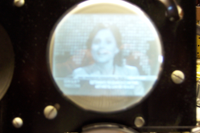
Here are some pictures of the restored set. The actual picture is NOT out of focus.

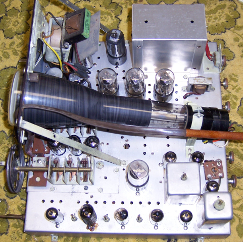
Top of Chassis below:

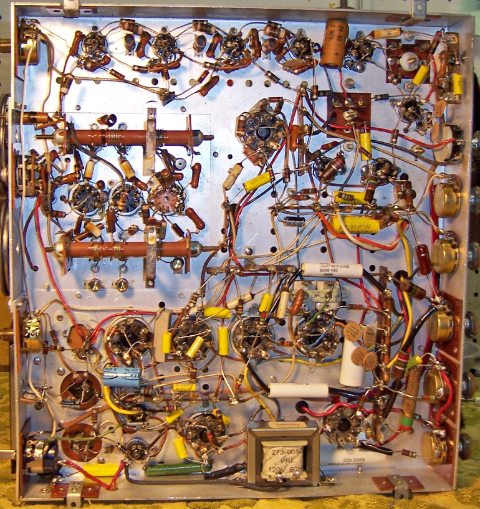
Chassis Bottom Below:

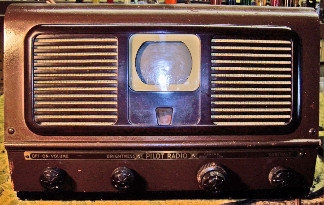
Completed Set:
