RCA Model 143 Cathedral Restoration
 |
The RCA Model 143 is a very large 8-tube superhet circuit radio that
receives long wave, medium wave, and two short wave bands. The cabinet has
a rounded top with shoulders - not really either a tombstone or cathedral
style cabinet. The schematic and a parts list for the radio can be found on-line
at Nostalgia
Air. Any part number references in the text below reference
the model 143 schematic listed as "Schematic with Fidelity
Change" (Riders page 5-86). There are several different
versions and a few changes documented in the RCA Service Notes in
Riders. |
My
antique radio restoration logs
Overview
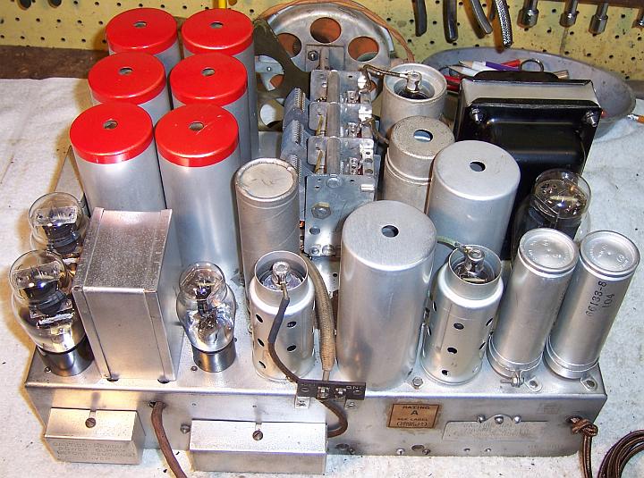
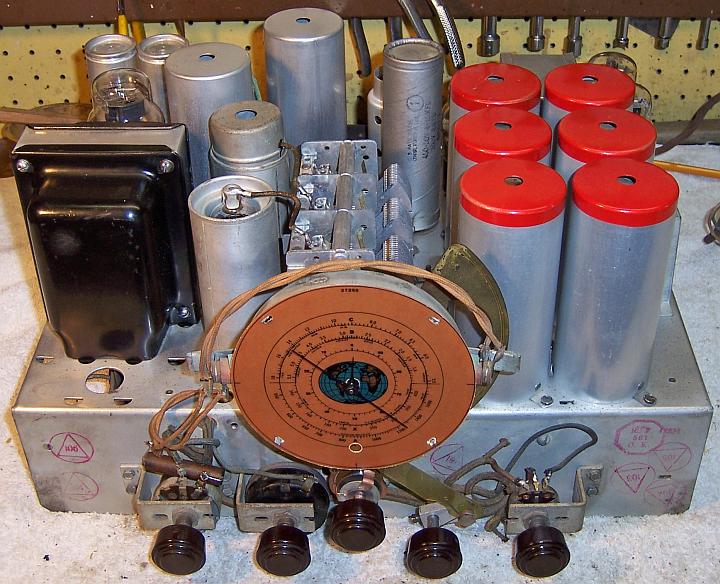
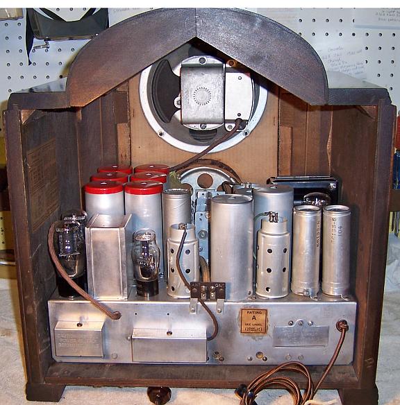
The radio was purchased on eBay. Externally it appeared to be all
original, complete and in excellent condition. It was listed as not
working, and the power cord had been cut off. All tubes, shields and
covers appeared to be in place. There was only minor corrosion on the chassis,
but it was VERY dusty. There was no rodent activity. This was
definitely the most difficult restoration I have even attempted. The
chassis was very cramped, and access to many components extremely
difficult. Partial disassembly was required in order to access some parts
for replacement. The chassis appeared to have been built in layers! For
example, there are quite a few parts that are UNDER the band switch. These
must have been installed before the band switch assembly was installed. Of course,
removing the band switch was not an option! Two large terminal boards contain
many parts that have to be changed - one board has parts on both sides.
The boards have to be removed from the chassis in order to replace parts
(neatly) and also to access parts underneath or to provide room to work.
Several transformers were installed using bent-over tabs which
are very difficult to straighten without danger of damage to nearby components.
One of the capacitor packs was riveted to the chassis. The two capacitor packs
and the driver transformer were all potted in tar.
Previous Servicing
I always attempt to avoid purchasing radios that have been
"restored" by collectors or flippers, and am looking for either all
original examples or those which have been "lightly serviced" in the
distant past by radio service shops. This radio met that requirement.
-
All resistors appeared to be original.
-
Only one wax/paper capacitor had been replaced: C58 0.01mfd
(tone control capacitor). It had been replaced by a 0.02mfd 600 volt Mallory
part (an older repair). All remaining capacitors were original.
-
The power cord had been cut off.
-
Six of the tubes supplied were RCA/Cunningham brand engraved
base types and likely original. The 5Z3 rectifier and type 75 2nd detector/AVC/AF
Amp were replacements (the type 75 had been replaced by a type 85 - a poor
substitute). All supplied tubes tested good (some were slightly
weak).
-
Two tubular filter capacitors had been tacked in under the
chassis. The original filter capacitors were still in place and were
still connected. They were both wet types, and later found to be
completely dry so that their removal was not necessary prior to bridging new
capacitors.
-
The 3-amp AC line fuse had been replaced by a 15
amp fuse.
Survey
-
The power transformer was tested. The AC voltage on both sides of the high voltage center tap was
balanced. Power consumption with no load was less than 10 watts, which
indicated that there were no shorted turns. I always perform this test
prior to restoration, even on working radios, since transformer overheating due to shorted turns or
other problems may not be obvious with only brief testing. Many
collectors new to restoration often completely recap a radio, and even
replace resistors and tubes, only to find out they have a bad power
transformer after completion.
-
All RF and IF transformers and coils tested OK.
-
15 dogbone
resistors were out of tolerance (by more than +/- 20%). A few others were
close (21-23%) and were not in critical circuits and would be left in place
(example: AVC decoupling resistors)..
-
The pilot lamps were both burned out.
-
The pilot lamp diffusers had small holes burned in them, perhaps
due to using lamps that were too large?
-
The speaker field and output transformer were OK.
-
The dial scale was very dark, which is typical of RCA/GE
radios of this vintage.
-
The driver transformer T2 (and enclosed reactor L29) was
unfortunately bad. The primary (in series with L29) measured open The
secondary was OK. Either the L29 reactor or the transformer was
defective. Surgery would be required to tell which was defective.
-
The 75 tube grid cap lead was shorted to the shield due to
deteriorated rubber wiring.
-
The chassis mounting washers were bad and would have to be
replaced. There are two washers used in each position (8 total). The outside
diameter needed was 7/8" and height 3/8" (same as the CW4 washers
available from Renovated
Radios. However, the center hole must be 3/8" since a metal
spacer is used. The center hole in the CW4 washer is only 1/4".
Cleaning
The chassis was very dusty, but not rusty. The dust was then blown off
of the chassis with an air compressor. Parts to be rebuilt or repaired were then
removed to provide cleaning access: both filter capacitors, the two capacitor
packs, the driver transformer, and tuning capacitor and dial assembly (for
cleaning and replacement of mounting grommets). The
chassis was cleaned using GoJo (white) hand cleaner and 00 steel wool. The
chassis was then carefully vacuumed, and any remaining steel wool fragments
removed using a magnetized screwdriver and masking tape.
Restoration Strategy
Since all of the original parts (except C38) were still in place I decided to try
to maintain the
original chassis appearance to the extent possible. All
original capacitors would be rebuilt in their original cases (restuffed),
including the original
filter capacitors and capacitor packs. I planned on finding an original RCA
replacement for C38 in my junk capacitor stock, and restuffing it. I
do not replace mica capacitors, but may test them in place if possible (usually
this requires disconnecting one end of the capacitor).
Any out of tolerance
resistors would be replaced with the same types if available. When I replace a component, I
always remove the original part completely from a terminal. Other good components connected at the terminal are protected from heat using old medical
clamps (hemostats). Excess solder is then removed using a solder sucker in order to
expose terminal holes for reattachment of the rebuilt or replaced component.
Repairs
Driver Transformer T2
Unless this part could be repaired or replaced, restoration of
the radio would not be practical. Finding a replacement part would mean finding
an RCA 143 parts chassis - which is very unlikely. And even if found, the same
transformer may be defective on the parts chassis. It was initially not known if
the primary of the transformer or the reactor L29 was open, since they are in
series. I also have not found anyone who knows the correct ratio of the
transformer. The first step was to remove the transformer from the chassis
and attempt to remove the transformer and reactor from their case. As
usual with RCA/GE, the transformer assembly was potted in TAR!
Access to the bent tabs holding the transformer case is limited
by a terminal board, wiring, and other components. The first step was to remove
the terminal board. All leads and components were disconnected from the 10
terminals. The board was then removed. One of the nuts retaining one of
the board's studs was hidden underneath a covered two-lug terminal strip on the
rear chassis. Several paper capacitor also had to be removed in order to
access the transformer tabs. The tabs were straightened and the
transformer removed, with difficulty. As suspected, the transformer and reactor were potted in
tar.
The transformer was placed leads up on an old baking tray in a
250 degree oven for about 1 hour - until the tar appeared to be bubbling.
The contents were then dumped onto the pan and heated for another hour in an
attempt to remove as much tar as possible from the component. While still
hot, the transformer and reactor were removed from the pool of melted tar.
The components as well as the case were soaked overnight in mineral
spirits. The parts were then cleaned as well as possible using the original
mineral spirits followed by several washes with clean mineral spirits. The
driver transformer, reactor, and various supporting hardware were then retrieved
for inspection. One lead of the transformer was soldered to a lug on the
reactor.
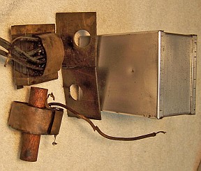
The reactor L29 was OK - it measured about 3100 ohms. The
primary of the interstage transformer was open. Having nothing to lose, I
did some further cleaning of the transformer and removed all of the E and I
laminations for access
to the coil. I removed the outer layers of the coil's insulation, exposing the
connections from the wire leads to the windings. But I never found the
internal winding lead that was supposed to connect to the primary wire.
And the more I dug, the more damage occurred. So I eventually gave up on
the original transformer.
I was now facing the task of replacing the original
transformer. But I did not know its turns ratio or other
specifications. It was about the same physical size as a Stancor A-62C or
A-63C. However, the winding DC resistances of the Stancor transformers
were very much lower than that of the original transformer (only the secondary of the
original was good
and could be measured). I had an A-62C transformer in stock which was good. It has a
1:2CT ratio, and it and the inductor L29 would both fit easily in the original
can. My concern was that the lower DC resistance of the Stancor
transformer may imply lower inductance, and thus loss of fidelity. I have
experienced this effect on many other radios of similar vintage, such as the GE
S-22, RCA Radiola R-7, and Crosley 124. Another concern using this transformer
was that since its primary DC resistance was much lower than the original, it
may not work well with the inductor L29 in series. And also its ratio
1:2CT may not be correct.
One other possibility available was a Halldorson HVAT-2 universal
driver transformer. The HVAT-2 is a large transformer with lots of iron
and lots of copper. It handles either single or push-pull primary and
secondary. Push pull to push-pull ratios of 1:1, 1:2 and 1:3 are
available.
For single ended driver stages, many more ratios are available such as
1:1.2, 1:1.5 and 1:6 by selecting appropriate pairs of primary leads. The
DC resistance of this transformer's primary and secondary were similar to the
original transformer. For example, using a ratio of 1:2CT:
| |
Primary |
Secondary |
| Original |
1835 |
2270 |
| HVAT-2 |
1620 |
2580 |
With its abundance of iron, it should provide
excellent fidelity. The problem was that if this transformer was used,
there would NOT be room in the original case for the reactor L29. It was
not obvious to me what the purpose of L29 was. Could it be eliminated?
Being a large bank wound air-core coil with lots of Litz wire (3100 ohms) it
would have some
affect on high audio frequencies. I posted this question on Antique
Radio Forums. The most likely answer I got back was that the purpose of L29
was to roll off the 10 kHz adjacent channel heterodyne whistle often present
during nighttime skywave conditions where distant stations come rolling in that
are only 10kHz away from local stations. That was also my original suspicion.
By using the HVAT-2 transformer and eliminating L29 I could
make all the primary leads available for access until the radio is restored, and
then pick the turns ratio based on the best sound of the radio. It is NOT
practical to remove and then reinstall the transformer after restoration, as
many components and connections have to be undone in order to access the
bent-over transformer tabs (which will eventually break off if flexed several
times). So I decided to go with the HVAT-2 transformer and eliminate
L29. The transformer initially was installed with the ratio of 1:2CT.
If it turned out that L29 was really needed, I could install it under the
chassis somewhere (outside of the T2 case). New leads were used, since the
originals were very stiff and would likely break if flexed. Not all the original
colors used were available in modern cloth covered wire, so some other colors
were used. No tar or rosin was used to seal the transformer in the case -
only strips of paper towel to hold it securely (the HVAT-2 is vacuum
sealed). Here is the repaired transformer:
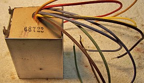
The ends of the unused leads were insulated with shrink tubing and left in place, should a
future owner wish to change the ratio from 1:2CT to 1:1, 1:1.2, 1:1.5, 1:3, or
1:6. A chart of available ratios vs. wire colors will be kept with the radio.
Resistors
The radio used older style "dogbone" type
resistors. Thirteen quarter watt, one half watt, and one 1 watt were out
of tolerance. All were wound
end types (lead wires wrapped around the ends of the carbon rod element and then the wraps soldered
together). Two of the quarter watt resistors were in spaghetti sleeving, and
thus normal 1/2 watt carbon composition resistors could be used to replace them,
since they are not visible. I keep a stock of NOS and used "dogbone" resistors, and buy all I can
on eBay and at radio swap meets (when reasonably priced)! Of course, most of these resistors, even NOS resistors, have also
drifted in value and no longer have their marked values. My solution is to
find a replacement resistor of the correct value and size as measured (ignoring the
markings), and then repaint it to the needed value codes using enamel hobby
paint! I was able to find suitable replacements for all of the
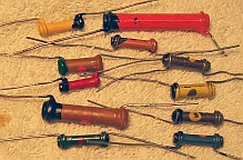
dogbone resistors. The replacements were repainted using
hobby enamel paint to the color codes of the original resistors. Here are
the replacement dogbone resistors (only five needed to be repainted) - some NOS
parts in my stock were still in tolerance:
Paper Capacitors
All paper capacitors were either tubular types with their ends sealed
with tar, or were in capacitor packs with multiple capacitors inside.
All individual paper capacitors were rebuilt in their original cases using
modern 630 volt film capacitors in order to maintain the original under-chassis
appearance. Most capacitors were typical early RCA tubular capacitors,
which have no markings other than the part number. The part number on the
capacitor apparently bears no obvious relationship to the part numbers in the published
parts list! I remove each capacitor from the radio by unsoldering its leads.
The lead lengths and use of any insulating sleeving lengths are then noted. I
take notes of which lead goes where in the radio, and identify the capacitor
using marking tags (which note the part identification and the location in the
notes where it was removed).
The tubular types are very easy to restuff. I simply pull the leads out
of each end. This usually also removes most of the tar used to seal the
capacitor. The capacitor foil roll is then pushed out one end. Any
tar remnants are removed using an Exacto knife with #11 blade. I then place the cleaned
up cardboard cover over a small alcohol lamp to melt any wax or tar left on the
outside, and then wipe it off with a paper towel (this also removes dust and
dirt). Leads of the replacement
axial film capacitor are then extended if needed (referring to the original
component lead lengths). The replacement capacitor is then wrapped in a
strip of paper towel cut to the width of the replacement capacitor. Enough
is wrapped around the capacitor to hold it securely inside the cardboard tube
and to center it.
Then ends of the restuffed capacitor are then sealed using melted rosin
salvaged from servicing early RCA Superhet catacombs, which melts at a fairly
low temperature. Other restorers have used hot melt glue or even caulk to
reseal capacitors. The original insulating sleeve, or a replacement (black
spaghetti tubing) is then installed. Finally, the capacitor is tested
before installation in the radio.
One capacitor, C59 rated at
400pf (voltage unknown) when removed from its case was found to be a mica type capacitor and
tested OK (380pf with no leakage). It was reused - reinstalled in its
original cleaned up case and sealed with rosin. There were several others
of the same type with different values. These all tested good and were
also assumed to be mica capacitors. All the remaining capacitors of this type
were left in place and re-used after testing (by disconnecting one lead).
One original RCA wax/paper capacitor had been replaced (C58: the tone control
capacitor, 0.01mfd). I noted that there were two other 0.01mfd capacitors in the
radio. Their RCA part numbers were 69037G2 and 69061G2. I found an
RCA 69037G3 in my junk capacitor box. This part was restuffed and used to
replace the missing RCA part C58.
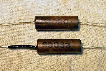 |
|
Restuffed RCA Tubular Capacitors
|
Capacitor Packs
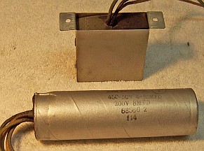
There were two capacitor packs used in the radio. One was a small
rectangular metal cased unit with wire leads containing C51 (0.5mfd unknown high
voltage) and C42 (a 10mfd 25 volt electrolytic). This unit was riveted
to the chassis. The rivets were drilled out and the capacitor opened up, tar
removed, and
restuffed using a 0.47mfd/630 volt film capacitor and a 22mfd/50 volt
electrolytic. The two replacement capacitors were first wrapped in shrink
tubing, then with strips of paper towels to center them in the original
case. Melted rosin was then poured into the assembly. The existing wire
leads as well as the original cardboard cover were reused. The capacitor was reattached to the chassis using
6-32 hardware.
The other capacitor pack was a clamp mounted cardboard case dry electrolytic
with wire leads. This capacitor contained C45 (10mfd @ 50 volts), C46
(4mfd @ 450 volts) and C55 (8mfd @ 200 volts). The original
capacitor parts were sealed in tar. The components were removed from the
cardboard case by heating the outside of the case with a heat gun until one of
the capacitors could be pulled out by its leads. Once one capacitor was
removed, the remainder of the parts as well as the tar could be cleaned out
mechanically. It was restuffed with
22mfd/50 volt, 4.7mfd/450 volt, and 10mfd/450 volt electrolytics. One of
the five leads is in common with two of the capacitors, as shown in the
schematic in Riders (make sure the polarity is correct!). The replacement parts
were secured using shrink tubing then wrapped in strips of paper towel to secure
and center them in the original case. Melted rosin was then poured in to
secure the capacitors in the original case. The
existing wire leads and well as the original cardboard bottom cover were reused.
Filter Capacitors
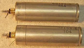
The original filter capacitors C53 and C54 were still in place. The original capacitors
were both 10mfd wet type clamp mounted units - working voltage unknown. There was
plenty of room inside the case for mounting replacement capacitors. The restuffing process for
this capacitor was as follows:
- Each capacitor was mounted in my small Unimat lathe held in the 3-jaw chuck and secured in place on the opposite end with the live
center. It was then deeply scored about 1"
above the base (almost through the case). I finished the cut with a fine tooth hobby razor
saw.
- The center electrode foil was removed, but the aluminum center stud was
retained and cut short. A hole was drilled into the center stud and a
solder lug was attached using a 4-40 brass screw and nut.
- The plus lead of the replacement capacitor (10mfd, 450 volts) was attached to the solder lug.
- The negative lead of the replacement capacitor was extended using #22 solid
bus wire and insulating spaghetti tubing through a drilled hole in the side of the
capacitor near the base. This lead would contact the chassis when the capacitor was
installed in the radio (held by the mounting clamp).
- The two halves of the case were then reattached using 3/4" PVC
plumbing couplings and epoxy. If the cut is done cleanly, the cut is
hardly visible after reassembly. I normally add a few layers of
masking tape around the PVC coupling to take up any excess space.
Tuning Capacitor
Prior to removing the tuning capacitor, the dial lamp sockets, the dial
pointers, dial scale, dial pan, dial lamp diffusers, anti-backlash gears and vernier drive assembly
were removed for cleaning and
lubrication.
The tuning capacitor had to be removed from the chassis for cleaning and to
replace the deteriorated mounting grommets. Removal was very difficult and
somewhat dangerous. There were four braided ground leads soldered to lugs on the
chassis and five more soldered to the brass rotor grounding fingers (these
braids went through holes in the chassis to grounding points underneath).
These braids were disconnected from the fingers, leaving the under-chassis
connections intact. The three stator connections were made using thick bus
wire, the other end connected to lugs on the band switch! One must use
extreme care here to avoid breaking the band switch.
After removal from the chassis, the tuning capacitor was cleaned in my old
Heathkit ultrasonic cleaner using dilute ammonia. Since the entire unit could
not be cleaned all at once, several cleaning steps were done, with the capacitor
at various angles. After this, the capacitor was cleaned using soap,
water, and old toothbrushes. It was then dried using a heat gun.
The mounting grommets were replaced using GLg-Philco grommets available from Renovated
Radios. These are slightly too thick, but have the correct center
hole and chassis mounting hole diameters.
The vernier drive assembly was cleaned in my old Heathkit ultrasonic cleaner
again using dilute ammonia followed by soap, water, and toothbrushes. It was
then dried using a heat gun and was lubricated using automotive distributor cam
lubricant (grease). The assembly could not easily be disassembled for
proper cleaning and lubrication. The two halves of the assembly were riveted
together! In addition, other parts were pressed or swaged together and
could not be removed without damage. After the cleaning and drying, as much lube
as possible was coaxed into the assembly using a toothpick. It seemed to
work OK at the time. I will know more after the set is back
together. The anti-backlash gear and spring was also not working properly,
even after cleaning and lubrication. It appeared that the spring was not
properly engaging the gear. Only a small amount of rotation would cause
the gear to slip and disengage with the spring. Like the rest of the
assembly, everything was pressed together and could not be disassembled without
damage. I'll just have to live with it the way it is.
The dial scale was replaced using a new reproduction dial available from Mark
Oppat at http://www.oldradioparts.net/dials_intro.html
(part #27255). Holes in the dial lamp diffusers were repaired using scrap
plastic and GC Service Cement. I was unable to determine the correct pilot
lamp to use (#40 or #46). Some Antique Radio Forums readers advised using #50.
I suppose that a #50 lamp would run cooler than a #46, since it draws .22 amps
at 7.5 volts. I was concerned that the dial could be damaged by using the wrong
bulb (I have seen too many Zenith black dial sets with holes burned in the dial
scale). The diffusers on my radio already have holes, perhaps normal due to age
and use. I did not have any #50 bulbs in stock, so I installed #46 bulbs.
75 Tube Grid Lead
The grid lead to the 75 tube cap was found to be shorting to the shield. The
inner conductor was rubber covered and had deteriorated. All shielded cable in
this radio had a cloth outer covering. I wanted to try to reproduce this
cable if possible. I found a suitable piece of shielded cable in my junk box.
The outer braided shield was bare. I was unable to reuse the original
outer cloth covering. So I used the outer cloth covering of a piece of
cloth covered power cord. I measured the original cable and attempted to
reproduce it, since this cable is very visible on the back of the
radio. The reproduction turned out OK, even including the cloth tags
where the outer cover was penetrated and the inner lead pulled through.
The color is close but not the same as the original (on the other hand, the
original had likely faded).

Other Repairs
The type 85 tube was replaced with the correct type 75. All other tubes
were left in place, since they tested good (or only slightly weak).
The power cord was replaced by modern reproduction cloth covered cord, and an
old style acorn type plug installed.
The four top chassis washers were replaced by CW4 washers from Renovated
Radios. The center holes were enlarged using a 3/8" Forstner bit in
my drill press - results were not perfect but were acceptable. This
provided the needed clearance for the 3/8" steel spacers. The four
upper washers actually support the radio chassis, and were totally flattened as
found. The bottom washers bear no weight and were reused, even though they
were deteriorated.
Cabinet
The cabinet was in very good shape but with a few scratches and
dings. It was cleaned with GoJo hand cleaner and 00 steel wool, followed by a coating of Johnson's Wax.
The front of the cabinet was slightly loose and was re-glued.
Testing
After the radio was completely reassembled, power was applied through a
wattmeter and fused Variac. Power was brought up slowly while monitoring
the B+ voltage and the wattmeter. The radio came alive and worked well on
all bands - no assembly errors which is amazing considering the complexity of
the radio and the degree of disassembly needed to access parts for replacement! The radio sounded great with the initial driver transformer ratio
of 1:2CT. I later tried the 1:3CT ratio, but could not tell any difference
in either volume or fidelity. I left it connected as 1:3CT.
The radio was then
aligned. Although the radio worked very well before alignment, many of the
adjustments, including the IF transformers, were not even close to
specifications. Some of the alignment frequencies used were unusual.
For example, on band B the signal generator and dial are to be set to
5160kHz! I have a frequency counter which I use to set my generator to the
required frequency, since its dial calibration is not all that accurate.
But I do not know how I was supposed to set the radio's dial to 5160 if the dial
resolution is only 100kHz at that frequency! Why not use 5100 or
5200? What is magic about 5160? Needless to say I had to estimate
the pointer position. I was able to set the all the bands at the given
alignment frequencies (but they were off slightly at other places on the dial)
even though the padder and trimmer adjustments had been done correctly..
I felt that the120Hz hum level was excessive, even though the filter
capacitors were doing their job, and were the correct values. I was advised
by the good people on the Antique Radio Forums to check the balance of the
output tubes. When I did, I discovered that one of the 42 output tubes had
failed - it lit up normally, but had zero emission. It tested good during my
initial survey and initial testing! Once it was replaced,
the excessive hum was gone.
Restoration Results
Most of my restoration objectives were met, but not all. There was no
intention of restoring the set to factory new appearance! My objective is
usually to reverse any prior servicing and make the radio appear to have never
been repaired. I do not go so far as to artificially "age"
solder joints, as do some collectors! Nothing gives away a restoration
faster than bright and shiny solder joints. Here are some of my
"misses":
- The leads to the driver transformer T2 were replaced, but some of the
original colors used are not available.
- The cloth covered replacement AC line cord was similar to the original,
but not exactly the same.
- The patch I made to the dial lamp diffusers was slightly visible through
the dial. I did not have the same color patch material
available. Even if I did, the glue used to attach it would likely have
been visible.
- The anti-backlash gear train could not be repaired, but this really only
affected the "split second" dial pointer, which is usually used to
return to stations that are close together on the main tuning dial.
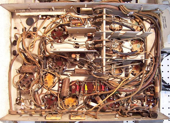
Chassis Before Restoration
|
 |
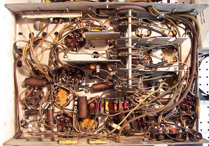
Chassis After Restoration
|
 |
