
My antique radio restoration logs
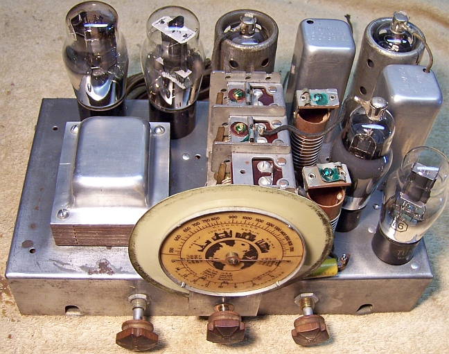
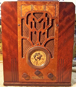
This radio was purchased on eBay. The cabinet, grille cloth and knobs were in fair condition. The cabinet had a couple of narrow strips of veneer missing on the top back, and a few joints and some plywood laminations were loose and needed re-gluing. The radio was sold as not tested. The radio is a six-tube AC superhet circuit radio with broadcast band and one short wave band in a tombstone or upright style cabinet. The radio does not have an RF amplifier stage, but does have a tuned pre-selector for the broadcast band only (3-gang tuning capacitor).
The original power cord was connected to a small surface mounted two-pin AC receptacle on the inside of the cabinet. Whatever plugged into that receptacle was in series with the AC power to the radio. Perhaps some sort of voltage reducer, or even some sort of fuse, was plugged in originally. Two longer pieces of power cord (of different types) were spliced on. A standard AC plug was used. As found, no power could have reached the radio if it were plugged in (which is good). The only identification found on the radio was a brass name plate below the dial which read "Silver Marshall Manufacturing Co.". There was no model number found on the chassis or cabinet. There was a paper label on the rear chassis which had what was perhaps a serial number "No. 621204" and the standard RCA license verbiage.
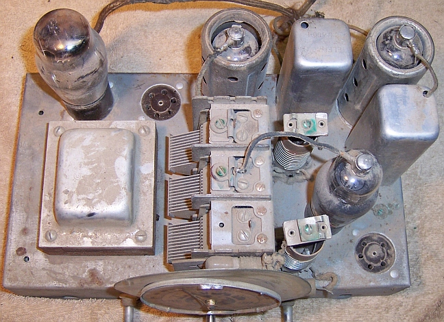
Two tubes were missing. Tubes installed were types 80, 75, 6D6, and 6C6. The two empty sockets were a 6-pin and a 5-pin standard base type. The 6C6 tube was plugged into the socket next to the type 80. The grid cap leads from the tuning capacitor center stator went to the 75 cap, and the 75 grid cap lead went to the 6C6. By examining the radio's wiring, the tube between the type 75 and 80 was likely a type 41 or 42 output tube (missing). The 6C6 was likely the mixer/first detector tube and in the wrong socket. The missing 5-pin tube was the oscillator, and likely a type 76. In the photo above, the existing tubes were placed in their correct locations. The likely tube line-up was:
76 oscillator
6C6 mixer
6D6 IF amplifier
75 2nd detector/AVC/First audio amplifier
42 audio output
80 rectifier
There were no Silver Marshall radios in Riders nor in RadioMuseum which matched this tube line-up. I next searched RadioMuseum using the tube list above and got matches for several brands of radios that used this tube complement (not all radios had schematics loaded). My chassis matched the 1935 Howard models E-14/E-107 almost exactly, including the tubes, the two bands and their tuning ranges, and a Candohm wire-wound resistor with 7 lugs. It is likely that Howard made this chassis and that it was used in several different cabinets and different brands of radios. This practice was quite common in the mid 1930's. So the schematic reference for this restoration will be http://www.nostalgiaair.org/PagesByModel/397/M0009397.pdf. I scanned a copy of the Riders schematic and enlarged the schematic part of the page. I then noted any differences between this schematic and my chassis. Differences were minor. For example, my radio had an AC line to chassis bypass capacitor - the Howard schematic did not. The output transformer shunt capacitor was .006 on the schematic. My chassis had an original .008mfd 2000 volt capacitor installed. The capacitor from the volume control center was .01mfd on the schematic, but my set had a .02mfd installed. There were other differences such as the resistance of the speaker field coil. I decided to use the Howard E-14 schematic for the restoration, but use parts values found in the radio vs. the schematic values if differences were found.
The radio had seen typical repair shop type servicing in the past. Most of the original components were still in place. There were no recent repairs based on the age of the replacement components used. I decided to try to reverse all previous servicing to the extent possible, yet get the radio working.
Three of the tubes installed were branded Raytheon. These were engraved base types (no date codes found) and may have been original. One other tube was branded Sylvania, and was likely a replacement. Two tubes were missing (42 and 76)..
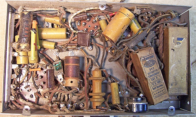
One wax/paper capacitor had been added. It was a 0.01mfd/600 volt capacitor connected from the 42 output tube plate to ground. This part was NOT on the schematic for the Howard E-14 and was not an original ARISTON brand capacitor. It may have been added to reduce the treble, since there is no tone control in this radio.
The original filter capacitor had been removed. Traces of where it was mounted were found on the chassis, which indicated its size and original mounting location. The original was a 8mfd+4mfd (voltage unknown) cardboard case capacitor with wire leads, and a common positive lead. Several tacked-in filters had been installed to replace it: a 5mfd/600 volt tubular electrolytic from B+ to ground, an 8mfd/600 volt rectangular box type capacitor (again from B+ to ground), and another rectangular box type capacitor (specification unknown - label missing) from B+ to B-. So it appeared that perhaps two different visits to the shop were made.
All of the original wiring and small resistors were still in place.
Several resistors had been tacked in parallel across two of the Candohm lugs: A 40K 1-watt dogbone, a 33K 1-watt dogbone, and an unknown wire wound resistor measuring 12.23K. The combination measured 6.88K ohms. This portion of the Candohm was the dropping resistor for the 6C6 and 6D6 screens grids and the 76 oscillator B+ supply. According to the schematic, it should have been 18K. Once these resistors were removed, it was discovered that that section of the Candohm was open.
A 4K 1-watt dogbone resistor was connected between two lugs of the Candohm: the lead to the cold end of the speaker field coil and the lead to the 6C6 and 6D6 screens and the oscillator (76) B+ supply. This made NO SENSE! It was removed and not replaced.
The original AC power cord had been cut short, routed through a two-pin AC socket mounted to the inside of the cabinet, and two different types of AC cord spliced on. The purpose of this AC socket was unknown, and it was not replaced.
My usual restoration procedure is to first make a complete survey of the condition of all components. The survey results guide my restoration strategy. I usually never apply power to a radio before restoration, even through a "dim bulb tester" or variac "to see if it works". If major and unique components are defective or missing and cannot be restored or replaced, I may elect to sell the radio for parts rather than to restore it. I always assume that all paper and electrolytic capacitors are leaky and thus should be replaced (I always "restuff" the original containers if possible). Any mica capacitors are assumed OK until testing proves otherwise.
Before starting repairs I made BEFORE photos of the chassis top and bottom. I use these photos to ensure that replacement parts and wiring are placed as close as possible to their original positions. Some radios are subject to problems (such as hum pickup or oscillation) if wiring is re-routed or lead dress is not the same as the original.
All of the tubes and tube shields were removed. The chassis was very clean, with no rust - just very dusty. Dust was was first blown off with an air compressor. The chassis top was then cleaned with a tooth brush and vacuum cleaner to remove any remaining dust. The tuning capacitor was removed for cleaning, and to replace the mounting grommets. The top of the chassis was then cleaned using GoJo (white) hand cleaner and 000 steel wool. Since this process may leave small steel particles, the chassis was then vacuumed carefully.
Wiring
The AC line cord was replaced with a modern reproduction cloth covered wire and old-style acorn plug. I prefer to use WI18POBR-C sold by Grand Brass Lamp Parts, since the separate inner leads are also cloth covered (rather than vinyl zip cord sold by other suppliers). Grand Brass also sells reproduction old style round acorn AC plugs.
Filter Capacitor
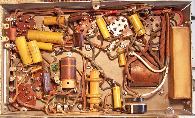
The original filter capacitor, according to the Howard schematic, was 8mfd and 4mfd, voltage unknown. The original had been replaced. I decided to use one of the replacement filter capacitors found in the radio to replace the original capacitor. It was a cardboard box type with wire leads and four mounting holes like the original. Unfortunately it was slightly too wide to fit in the original space. So I decided to mount it on the side of the chassis instead. It would then appear similar to the original capacitor and in the same general area. One end of the box (the one with the wire leads) was opened using a heat gun to soften the wax or glue. An inner cardboard sleeve was then removed, which contained the original capacitor parts. The sleeve was heated using a heat gun, opened up, and the old capacitor parts removed. The sleeve was cleaned and re-inserted into the outer container. A replacement capacitor was fabricated using a two 10mfd/450 volt electrolytics with their positive leads connected together. Separate negative leads were used. Heat shrink tubing was used as insulation between the capacitors and to cover the assembly. Spaghetti tubing covered the junctions between the capacitor leads and the capacitor's external wire leads. The wire leads were routed through the existing two holes in the case, and an addition hole was punched for the third lead. The flap and mating surfaces were then cleaned and the capacitor reassembled using melted rosin as glue. The rosin was salvaged from servicing RCA Radiola Superhet catacombs! The rosin can be heated and the capacitor opened up if needed in the future. The capacitor was mounted on the side of the chassis (under side) using 6-32 screws and nuts.
Paper Capacitors
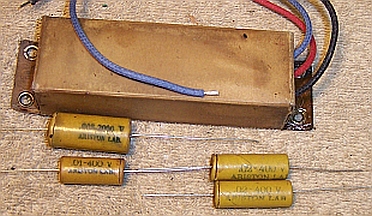
The original paper capacitors were all branded ARISTON. All were still present. All of these capacitors would be restuffed with new 630 volt axial film capacitors in order to maintain the original chassis appearance. When the capacitors were removed for restuffing, I noticed that the line bypass capacitor (.02mfd/400 volts) was wrapped in friction tape. When this tape was removed, I found that the capacitor had split open down the side - it appeared to have failed for some reason. This was hard to explain since there is normally no voltage across this capacitor unless a ground connection is attached to the chassis (the radio does have a separate antenna and ground lead). In any case, I could not use this capacitor case for restuffing. I maintain a stock of both branded (Zenith, Philco etc.) and unbranded (Sprague, CD etc.) dud capacitors for just this situation, or when an original part has been replaced. After searching my dud stock, I found several ARISTON brand duds. But I had no .02mfd/400 volt unit in my stock I decided to use an available .01mfd/400 volt unit instead, since the schematic shows no such capacitor being present. The case was restuffed using a .022mfd/630 volt film capacitor.
One other problem was restuffing the capacitor across the audio output transformer. This capacitor's purpose is to limit voltage spikes from static crashes which could damage the output transformer. It was original and was rated at .008mfd 2000 volts! I assume this was the peak voltage rating. In any case, I could not find a suitable new part with this rating that would fit inside the original case. After consulting with the good folks on Antique Radio Forums, I decided to use two 0.015mfd 630 volt film capacitors in series. This would result in a capacity of 0.0075mfd and 1200+ DC volts. Forum members stated that since the capacitor was across the output transformer primary rather than from the output tube plate to ground, that this voltage rating would be more than adequate. And even if the capacitor should short, it would do not damage to the output transformer or any other parts. The two 0.015mfd/630 volt film capacitors in series were covered using shrink tubing since they were touching each other. The combination would easily fit inside the original case.
ARISTON capacitors are somewhat difficult to restuff. Both ends of the cardboard case are crimped over cardboard discs through which the component leads pass (vs. the usual plain cardboard tube sealed with wax). In order to restuff them, I used the following procedure:
 |
|
Restuffed Filter and some Paper Capacitors |
Tuning Capacitor Grommets
The tuning capacitor grommets looked like standard black rubber grommets. They had deteriorated and were very stiff. They were replaced using standard vinyl grommets for a 1/4" clearance hole and 1/8" center hole. These were standard hardware store items. They worked, but were likely much stiffer than the original grommets.
Small Resistors
Only one small resistor was out of tolerance - the 42 tube grid resistor measured 25% high. It was a 1 megohm 1/4 watt dogbone type. I maintain a collection of used and NOS dogbone resistors of various sizes just for this situation. I just happened to have a 1 megohm 1/4 dogbone resistor that was in tolerance (980K ohms). This was used to replace the 42 grid resistor. The remainder of the small resistors were in tolerance.
Candohm Resistor
The radio contained a Candohm type metal clad wire-wound resistor with seven
lugs. According to the Howard schematic the resistance measurements were as
follows (lug 1 is the closest to the front of the chassis):
Lugs 1-2: 7K (measures 5.16K)
Lugs 2-3: 250 ohms (measures 324 ohms)
Lugs 3-4 No Connection
Lugs 4-5: 400 ohms (measures 425 ohms)
Lugs 5-6 No Connection
Lugs 6-7: 18K (open)
As found, several resistors were connected in parallel between lugs 6 and 7. The combination measured 6.88K. The schematic says that this section of the Candohm should be 18K ohms. This section of the resistor supplies B+ to the 6C6 mixer and 6D6 IF amplifier screen grids as well as the local oscillator (76 tube). Using a tube manual and typical operating points, the 6C6 and 6D6 screens should draw about 2.7ma total. The 76 oscillator should draw 5ma. So using a typical B+ of 250 volts and 18K for the Candohm section, the screen voltage would be 111 volts, which is reasonable. This 18K section would need to dissipate 1.067 watts. I had an 18K 10 watt resistor in stock, so I decided to use this resistor. Adjustments could be made after completion of the restoration, if needed.
I hesitated to use the existing Candohm terminals 6 & 7 to mount the replacement resistor (as found). This section of the Candohm carries the full B+ voltage. Should it short to ground, it could cause damage to the power transformer, speaker field, or other parts. Both terminals measured infinite resistance between them and also from each lug to ground. But this was using a DVM, which makes resistance tests using a low voltage. I repeated the test using my Sprague Tel-Ohmike TO-4 Capacitor-Resistor Analyzer in leakage resistance mode, which uses a high voltage for the test (designed to test paper capacitors for leakage). The leakage resistance measured 5000 megohms, but dropped to lower values as the test continued. So there was NO WAY I would trust simply bridging the two terminals of the Candohm.
Instead, I found a terminal strip in my stock that could be mounted just below the Candohm resistor. Its two lugs closely matched the spacing of the corresponding lugs of the Candohm. This meant that the existing wiring to lugs 6 and 7 of the Candohm could be used. The terminal strip was mounted by soldering its two mounting lugs to the edge of the chassis.
The cabinet side plywood laminations that were separating on the back sides were glued and clamped. Some loose veneer on the top back was glued to prevent further damage. The small slivers of missing veneer on the top back, which exposed light wood underneath, were colored using Walnut wood dye so that they were not so obvious. The cabinet was cleaned using GoJo (White) hand cleaner, applied and then wiped clean using Toolbox White Rags (soft, smooth paper towels made from rags).
Once the radio chassis was reassembled and the tubes installed, power was brought up slowly using a variac. A DVM monitored the B+. The radio came alive and worked well on both bands. The B+ measured 232 volts, and the 1st detector/IF screen and oscillator voltage was 98. So the 18K Candohm replacement screen dropping resistor was correct. The resistor was dissipating only about 1 watt as calculated, so a 10 watt resistor was overkill. I replaced it with a 2 watt wire wound resistor. The radio was then aligned. The IF alignment was way off. There were no other suprises.
Most restoration objectives were met. I was able to restore the radio to its original condition prior to servicing except for:
Chassis Bottom Before and After Restoration |
 |
 |
