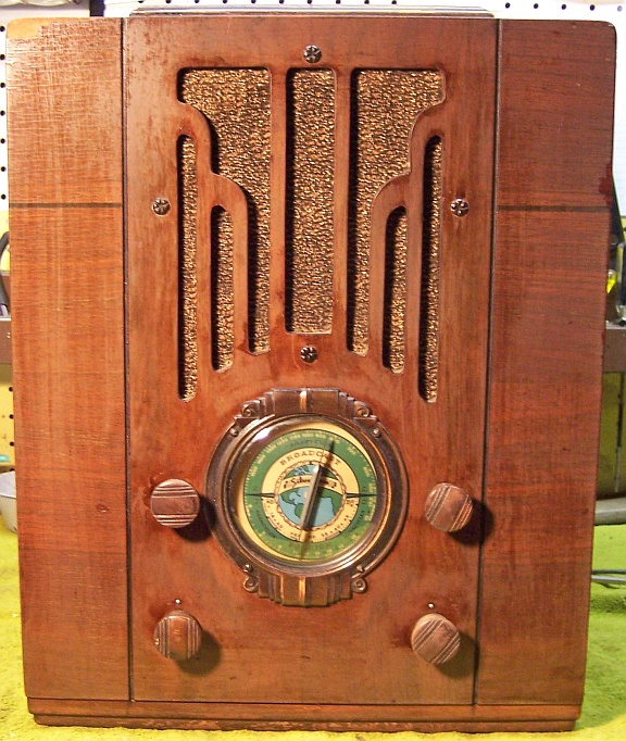
Silvertone Model 1938 Restoration
 |
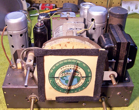
The Silvertone model 1938 from about 1936 is a 6-tube small
tombstone or upright style radio. It receives the standard broadcast
band and two short wave bands. This example had seen
minimal servicing in the past. I
decided to try to reverse any previous repairs and to retain the existing
above and below chassis appearance to the extent possible, and yet get it
working again.
The schematic for the Silvertone 1938 can be found on Radiomuseum.org. Any part numbers will refer to numbers on that
schematic (there is also a schematic on Nostalgia
Air, but the Radiomuseum schematic is more accurate). |
My
antique radio restoration logs
Condition As Found
This radio was purchased on eBay. The cabinet was in fair original condition, as were the
knobs and grille cloth - lots or wear, dings, scratches and finish loss.
The finish was cloudy or oxidized in areas. The top of the radio may have
been recoated with a dark stain or varnish. The radio was very dirty and dusty when
received - the dirt hid a lot of defects not visible in the eBay photos! There were a few nuts and
nut fragments inside, which was a bit worrying - this is often an indication of
rodent activity. However, there was no signs of any nesting, urine stains
or damage found. There was a fair sized
veneer chip on the top front. The
radio was sold as not tested. There was no external evidence that the radio had been
restored - even the power cord and plug were original. I always avoid knowingly purchasing a radio that has been
restored, as many collectors take shortcuts such as removing the original capacitors and filters. The original
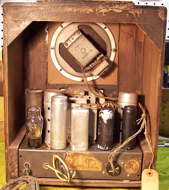
final inspection tag was still attached to the speaker cable.
Circuit
The Silvertone model 1938 is a 6-tube AC superhet circuit radio,
and the circuit is very unusual. This is one reason that I purchased it.
It was manufactured for Sears by Colonial
radio, and the build quality was quite high. The radio has no RF amplifier, but does have a
double-tuned pre-selector (3-gang tuning capacitor) to reduce image response due to the
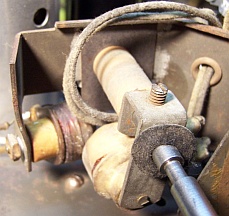
low IF frequency used (175kHz). The volume control system is very unusual: it varies the coupling between the primary and secondary of the
second IF transformer! I have seen this variable IF coupling used in other Silvertone radios
for variable selectivity or for tone control, but never before for volume control. Here
is the mechanism:
A sixth tube is used as a separate AVC stage - the
second detector and AVC functions are separate tubes. The signal level to
the second detector is varied by the volume control, but the AVC rectifier is
driven from the primary of the second IF transformer and thus is not affected by the
volume control. If this were not done, then reducing the volume would
reduce the AVC voltage and allow the radio to overload on strong signals. So in
reality, the weird and complex volume control method costs an additional
tube. The tube complement
is also unusual: a mix of standard base (big pin) tubes (84/6Z4, 75, 6A7) and
octal metal-glass tubes (6C5MG, 6K7MG, and 6F6MG).
Previous Repairs
-
The 6C5MG AVC tube had been replaced with a metal 6C5. The
6F6MG had been replaced by a 6F6G. The Silvertone 6K7MG tested weak but may
have been original to the radio. The remainder of the tubes were
likely replacements, since they were not branded Silvertone.
-
All paper capacitors were original (Sprague branded).
-
All resistors were original (all were dogbone style)
-
Two tacked in tubular electrolytic capacitors had been
installed under the chassis and were connected to the original filter capacitors, which were
still in place.
-
There was a small piece of metal (a shield) covering part of
the fixed secondary coil of the second IF transformer (which is part of the volume
control mechanism). Perhaps this was to reduce the coupling?
Survey
My usual restoration procedure is to first make a complete
survey of the condition of all components. The survey results guide my
restoration strategy. If major or unique components are defective or
missing and
cannot be restored or replaced, I may elect to sell the radio rather than restore it.
I always assume that all paper and electrolytic capacitors are leaky and thus should be
replaced (I always "restuff" the original containers if possible).
Any mica capacitors are assumed OK until testing proves otherwise. I
did not test the radio prior to restoration.
-
The speaker field and output transformer were OK
-
The power transformer was OK. The high voltage was balanced across the center tap (with
20 volts applied through a Variac) and power consumption was very low (about
5 watts) with full line voltage and no load.
-
The tuning capacitor mounting grommets were OK - unusual.
-
The chassis mounting bushings were bad - which is almost always the case. One was intact
and could serve as a model to find replacements.
-
All except three resistors had drifted and were now out of tolerance. All were
dogbone style - most were 1/4 watt size.
-
All RF coils were OK
-
The first IF transformer was OK.
-
The primary of the second IF transformer at first measured OPEN, and
later measured a high resistance (1300 0hms). This coil is part
of the volume control, which varies the coupling between the primary and
secondary of the second IF transformer, and if defective would be a
showstopper to restoration! I connected a 1.5 volt battery to the coil through a DVM
set for measuring current. The current indicated a calculated resistance in the 50 ohm
range, which was correct. I then measured again and this time it
indicated about 55 ohms. I suspected a bad connection or the coil was
simply fooling my DVM's ohms measuring circuit.
-
The 6K7MG tube was weak. The remainder of the tubes were good,
although not the correct types in some cases.
-
The AC switch (on the tone control) was not functional - dirty or oxidized
contacts were likely.
Repairs
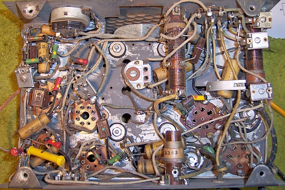
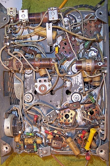
All tubes and shields were removed. I removed the tacked in filter
capacitors. I then took
a photo of the chassis
bottom so that routing of wiring and component placement could be restored.
Lead dress is often critical in radios. Since no parts had been replaced,
this photo should represent the original condition of the chassis, and thus the
desired appearance after restoration:
The dust was removed from the chassis using an air compressor. The dial
assembly and tuning capacitor were removed. The top of the chassis was cleaned with GoJo hand cleaner and 00 steel
wool. This process often leaves behind metal fragments which can cause
shorts, so I then went over the chassis with a small magnetic screwdriver to
retrieve them. The tuning capacitor (previously removed) was cleaned in an old Heathkit ultrasonic
cleaner with dilute ammonia. After drying, the bearings were lubed with
automotive distributor cam lubricant.
Resistors and Capacitors
All of the original Sprague paper capacitors were rebuilt in their original cases
using modern 630 volt film capacitors in order to maintain the original
under-chassis appearance. I reseal the cardboard tubes using rosin
salvaged from servicing RCA Radiola Superhet catacombs (it melts at a low temperature and will not damage
the replacement capacitors. When I replace a component, I
always remove the original part (or wiring stubs left over from past component
replacement) completely from a terminal. Other
components connected at the terminal are protected from heat using old medical
clamps. Excess solder is then removed using a solder sucker in order to
expose terminal holes for reattachment of the rebuilt or replaced component.
The original filter capacitors C9 and C20 were rebuilt in their original cases.
Both were originally 8mfd wet electrolytics. Both were now completely
dried out,
which is why they could be left in place (and paralleled with new capacitors)
with no problems. C9 had a cardboard insulating cover, since its case is
not grounded. The cover seemed firmly attached to the aluminum can -
likely glued. In a previous similar situation, I split the cover and was
able to remove it with minimal damage, although the split was very visible. This one had a
top cover in addition,
which also did not want to come loose and would prevent removal of the bottom
part of the cover. If the covers were firmly glued in place, they would be
destroyed by any attempt to remove them. So I decided to leave the covers
in place. Both capacitors were chucked into my small Unimat lathe using
the original mounting nuts from both units to hold them in the chuck (the nuts were installed
back to back). The capacitor terminals would otherwise have prevented
mounting them in the lathe. A live center was used to steady the other
end of the capacitor. The cases were scored deeply about 1" up from
the bottom of the cases - almost all the way through - and then the cuts were
completed using a hobby fine tooth razor saw. The positive electrodes were
removed down flush to the insulator. The cases were then cleaned
inside. The existing positive electrode stubs were drilled and tapped for a 6-32
screw and a ground lug attached inside the capacitor. The positive lead of
the replacement 10mfd 450 volt axial electrolytic capacitor was attached to the
ground lug. A small hole was drilled into the base adjacent to the threaded stud
for the negative lead of the replacement capacitor, which was extended and
insulated using spaghetti tubing.
Tubes
I was able to find replacement Metal-Glass tubes for the 6K7MG (which was
weak) and the 6C5MG (which had been replaced with a normal metal 6C5). The
only available 6C5MG I could find had about 30% of the paint missing! I
later found a 6F6MG and installed that tube.
Other Repairs
The tone control and switch was cleaned with GC Big Bath cleaner. The
switch then worked OK. The band switch was also cleaned using Big Bath.
The chassis washers were replaced using Silvertone chassis mounts (GS-1954)
purchased from Renovated
Radios.
Testing and Alignment
Once the radio was reassembled and the tubes installed, power was brought up
slowly using a variac. AC power consumption was monitored using a watt meter, and a
DVM monitored the B+. The radio powered up and the audio worked, but
there was no reception. It was discovered that the replacement 6K7MG tube had died -
the filament was open, even though the tube tested good when received from the
vendor. I reinstalled the original 6K7MG that came with the set, which
tested weak, but it worked OK. Later, I resoldered the pins of the
replacement 6K7MG, and it then tested OK.
The set was then aligned. There are NO oscillator adjustments on this
radio other than a broadcast band padder. The two short wave bands were very
close to correct dial calibration. But the broadcast band was about 50kHz
high. There was not much I could do about this.
The variable IF coupling volume control moving coil was returned to its as
found position. At minimum volume, there was still some sound heard.
I temporarily reinstalled the aluminum shield that was found originally
installed on the radio. It did reduce the minimum volume considerably, but was
very likely NOT original. There were instructions for improving minimum
volume performance found in Riders. This procedure was followed and the
result was satisfactory (but there was still some sound output at
minimum volume!)
There was severe modulation hum and resulting distortion on stations at the high end of the broadcast
band. There was no problem on the short wave bands or on the low frequency end
of the broadcast band. This is a common problem in my shop. My antenna is
indoors (strung from the basement ceiling), and there are lots of sources of interference, such
as electrical wiring, fluorescent lighting fixtures, wall wart power supplies,
computers, and other devices. Some radios have this problem, while others
do not. Zenith radios with shielded Wavemagnet (loop) antennas never seem
to have the problem. In the past, I have been able to eliminate or reduce
the problem by grounding the radio, moving it away from my work bench, reversing
the AC plug, installing a line bypass capacitor, or simply rotating the radio 90
degrees. But nothing seemed to work with this radio! The best cure
seemed to be connecting a 0.1mfd capacitor between the hot AC lead and ground
(center screw of a grounded electrical outlet). I was getting inconsistent
test results until I realized that the original line cord and plug were NOT
polarized, and thus reduction of modulation hum depended on which way the radio
was plugged in. I permanently installed a 0.1mfd 630 volt capacitor
between one side of the AC line and the chassis, and always ground the radio
when in use. This resulted in acceptable performance if the radio is
plugged in a particular way. Ideally there would be a line bypass
capacitor from both sides of the AC line to ground (chassis). However in
this case, one end of the AC line is directly connected to one lead of the power
transformer using a taped joint, and is thus not accessible without wrecking the
originality. The taped joint was also directly underneath one of the RF
coils. If I ever sell this radio, I will have to
remove the capacitor, since a user could get quite a tingle if he/she touches
the chassis that is not grounded!
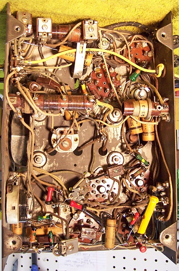
Restoration Results
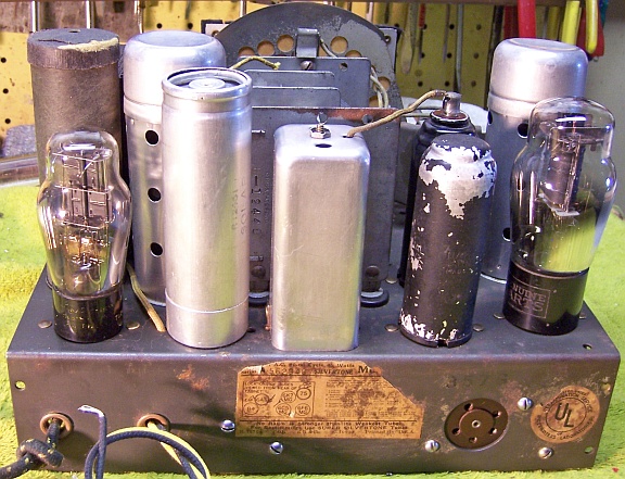
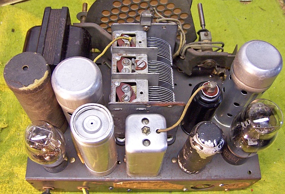
Non-original line bypass capacitor is not shown. The 6F6G tube has been replaced by a
6F6MG in the next to last photo (back view).
|
Chassis Before Restoration |
Chassis After Restoration |
 |
 |
