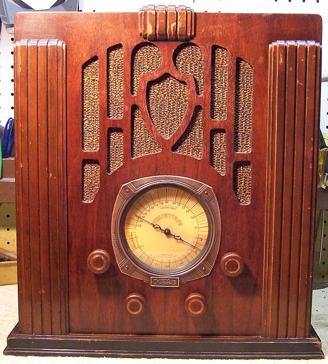
Truetone (Wells-Gardner) Series 7J Tombstone
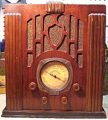 |
The Truetone Series 7J is a large 7-tube AC Superhet
circuit radio that receives the broadcast band and one short wave band.
Truetone was a brand sold by Western Auto Supply. This particular radio
was made by Wells-Gardner (W.G. 24). The radio had seen some servicing in the past.
There was a radio shop label still on the cabinet. Three wax-paper capacitors
had been replaced, the power cord replaced, and some tubes likely had been
replaced. Since the radio was still largely original, I decided to try to
get it working yet maintain the
original top and bottom chassis appearance and to reverse any previous
repairs to the extent possible.
The schematic for the radio can be found on Nostalgia
Air. Any part numbers will refer to numbers on that schematic. |
My
antique radio restoration logs
Overview
This radio was purchased at the 2014 CC-AWA Antique Radio Conference and
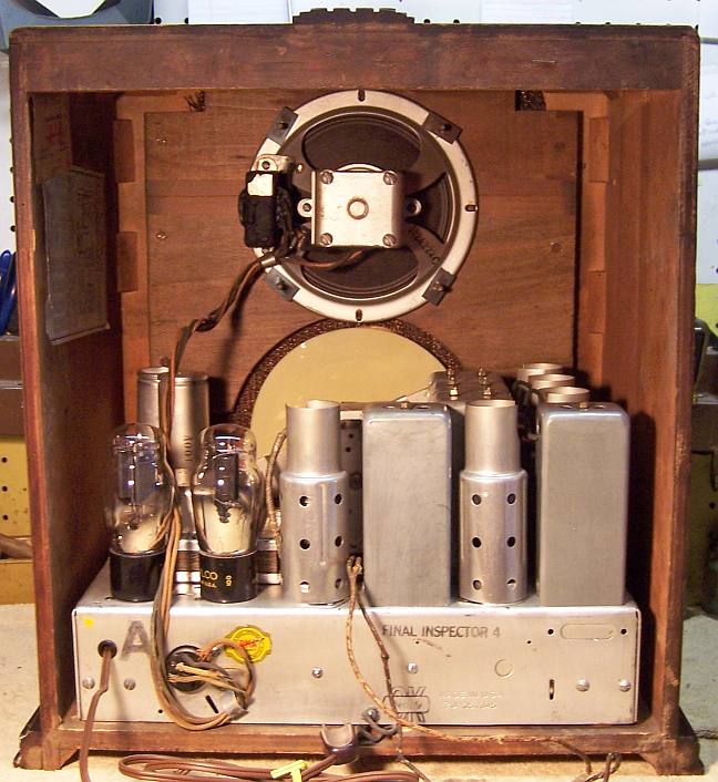
Flea Market in Charlotte, NC. Being made by Well-Gardner, the build quality is very high. The working status was not stated by the seller. The cabinet
finish, grille cloth, and knobs were original and in good condition. All
tubes and tube shields were in place. The often missing chassis retainers
(L-shaped and threaded) were in place, as were the chassis cushions. There were
no shipping bolts present.
Previous Repairs
The radio had seen a minimal amount of repair in the past, and
all repairs were far in the past, judging from the vintage of the components used. This
was a well loved radio that someone paid a lot to have repaired.
-
Three wax-paper capacitors had been replaced. In this radio
this is a difficult task, since all tubular wax-paper capacitors are secured
by clamps (fortunately held by screws rather than rivets).
-
The original filter capacitors were still in place.
-
It is likely that some or perhaps all tubes had been
replaced. Three were branded Wizard, three branded RCA, and one branded
Philco. The Wizards may have been original.
-
All of the original resistors were still in place.
-
The line cord had been replaced.
Survey
My usual restoration procedure is to first make a complete
survey of the condition of all components. The survey results guide my
restoration strategy. If major and unique components are defective or
missing and
cannot be restored or replaced, I may elect to sell the radio rather than restore it.
I always assume that all paper and electrolytic capacitors are leaky and thus should be
replaced (I always "restuff" the original containers if possible).
Any mica capacitors are assumed OK until testing proves otherwise. I
never apply power to an unrestored radio, even through a variac or "dim
bulb" tester.
-
Seven resistors were out of tolerance (more than +/-20%). All were
old style dogbone
type resistors of various wattages.
-
The speaker cone, field coil, and output transformer were
OK.
-
The power transformer was OK. The high voltage was
balanced across the center tap with 20 volts applied through a variac.
With full power applied (no tubes present), the wattage consumed was less
than 10 watts. A transformer with shorted turns will draw excessive
power and will heat up. I use a real analog watt meter for these
tests.
-
One pilot lamp socket was missing (the power lead was still
in place).
-
The wire wound resistor R13 was fortunately good and in
tolerance.
-
All RF coils and transformers were OK.
-
The IF transformers were OK.
-
All tubes were good.
-
The chassis cushion washers still OK.
-
The tuning capacitor mounting grommets had hardened and
shrunk, allowing the capacitor to move around.
-
All wiring was cloth covered and was OK.
-
All tube shields were present.
-
The pilot lamp was burned out
Repairs
The chassis was very dirty. All tubes and shields were removed and dust was removed using an air compressor.
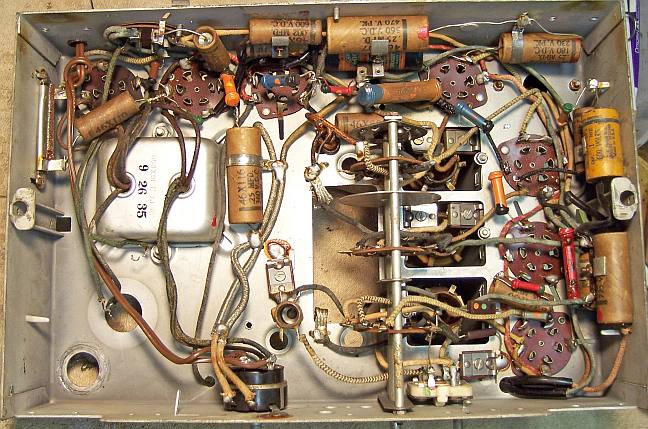
Before starting repairs, I took photos of the chassis bottom so that routing of wiring and component placement could be restored.
Lead dress is often critical in radios. The tuning capacitor was
removed for cleaning and for replacement of the mounting grommets. The two
can type filter capacitors were removed for restuffing and chassis access for
cleaning.
I then removed all
of the non-original capacitors, documenting their locations
and connections. When I replace a component, I
always remove the original part completely from a terminal. Other
components such as mica capacitors and in-tolerance resistors connected at the terminal are protected from heat using old medical
clamps (hemostats). Excess solder is then removed using a solder sucker in order to
expose terminal holes for reattachment of the rebuilt or replaced component.
The top and sides of the chassis were cleaned with GoJo hand cleaner and 00 steel
wool. Since this process may leave metal residue, I then went over the
chassis with a vacuum cleaner followed up by a small magnet and masking tape.
The tuning capacitor trimmer hardware and mica insulators were removed to
prevent damage during cleaning. I noted the original positions of the trimmer
adjustments so that they could be returned to the original positions. I do this
by counting the number of half-turns of the adjustment screw to fully tight. The tuning capacitor was
cleaned using in my old Heathkit ultrasonic
cleaner using dilute ammonia, followed by soap, water, and old toothbrushes. After drying, the
bearing surfaces were lubed with automotive distributor cam lubricant. The tuning capacitor grommets were replaced by
GLg-Tuner grommets from Renovated
Radio, thick side up. These worked OK, but the center hole was
slightly large and allowed some movement of the capacitor. These grommets
were also slightly too short, so flat washers were added between the capacitor
body and the grommets.
Capacitors
Filter Capacitors
The original wet type filter capacitors were still in place. One (C25,
14mfd/400 volts) was insulated from the chassis. The other (C26, 18mfd/300
volts) was not insulated from the chassis. I was able to remove C25 easily
using a large socket wrench. But the threads on C26 were stripped and I was NOT
able to remove the part. I was forced to cut off the body and then grind
off the remainder of the capacitor. I found a similar part in my junk box
to replace it. Both capacitors were restuffed with suitable new
electrolytics. I used 15mfd/450 volts for C25, and 22mfd/450 volts for
C26.
Here is my restuffing process for these wet type electrolytics:
- The capacitor was mounted in my small Unimat lathe held in the 3-jaw chuck
by its mounting nut and secured on the opposite end by my live center.
The capacitor is held by the nut to prevent damage to the threads.
- The case was deeply
scored about 1" above the base (almost through the case). I
finished the cut with a fine tooth hobby razor saw. In this case, there was
no liquid inside to be slung out as the capacitor was turned in the lathe. If the cut is done cleanly, the cut is
hardly visible after reassembly.
- The center electrode foil was removed, but the aluminum center stud was
retained and cut short. A hole was drilled into the center stud and a
solder lug was attached using a 4-40 brass screw and nut.
- The plus lead of the replacement capacitor was attached to the solder lug.
- The negative lead of the replacement capacitor was extended using solid
bus wire and insulating spaghetti tubing through a drilled hole in the base
of the capacitor near the threaded mounting stud.
- The two halves of the case were then reattached using 3/4" PVC
plumbing couplings and epoxy. I normally add a few layers of
masking tape around the PVC coupling to take up any excess space.
- Once the epoxy had hardened, the original grounding lug and insulators
were reinstalled. In the case of C25, the negative lead of the replacement
filter capacitor was attached to the grounding lug after the capacitor was
mounted. In the case of C26, the negative lead was trapped between the
capacitor body and the chassis.
Wax-Paper Capacitors
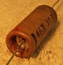
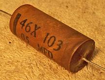
All the wax-paper capacitors in the radio were marked with a part number
starting with 46X, and also marked with the value and voltage rating (normal and
peak). The capacitors used by Wells-Gardner are unusual in that their voltage
ratings are values such as 180, 240, or 360 volts etc. Their construction is
also unusual. The capacitor is assembled inside a cardboard tube, the ends of
which are crimped. Inside both ends is a metal disc, to which the component
leads are soldered. The foil roll is soldered to an extension of each lead on
the inside. The tube is filled with wax (and in one case, with tar). These
capacitors are difficult to restuff without the repair being visible. There is
really no way to "uncrimp" the ends without making a mess. My
restuffing process is as follows:
- The original lead length required is documented.
- One end of the cardboard case is removed using a sharp single edge razor
blade. The cut is done as close as possible to the end, and great care
is taken to keep the cut line straight.
- The cardboard case is then heated using a heat gun. The part is held using
pliers by the lead on the opposite end.
- While warm, the outside of the cardboard tube is wiped clean using a paper
towel.
- The case is held using a paper towel and the lead on the cut end is
pulled. This will remove the metal disc as well as one component lead
and will break the connection to the foil roll.
- The case is then again heated with the heat gun and the contents pushed
out from the opposite end (I use a small socket wrench for this purpose - it
is hollow inside to accept the component lead). The contents are then
discarded.
- The component lead on the cut end is cut flush with the metal disc, and
then unsoldered from the disc. The center hole in the disc is cleaned of any
solder so that replacement leads can be attached.
- If the lead length required is longer than those of the replacement
components, the leads are extended using buss wire. The splice is made
close to the body of the replacement part so that the splice will not be
visible.
- The metal disc previously removed in step 7 is inserted back into the
cardboard tube in its original orientation.
- The replacement capacitor is wrapped with a narrow strip of paper towel in
order to center it in the tube, then one end of the replacement capacitor is
passed through the center of the metal disc and soldered to the disc on the
outside.
- The cut end of the tube is then filled with melted rosin salvaged from
servicing RCA Radiola Superhet catacombs! Some collectors use beeswax
or even hot glue to secure the part in place.
Three original capacitors had been replaced: C6 and C21 (0.1mfd/360 volts)
and C9 (.25mfd/240 volts). I collect both branded (Zenith, Philco, etc.) and
generic dud capacitors. However I did not have the correct original
Wells-Gardner parts in stock. For C6 and C21 I used Wells-Gardner part number
S46X98 (.1mfd/180 volts) restuffed using 0.1mfd/630 volts. For C9 I used
part number 31077 .25mfd/400 volt restuffed using 0.22mfd/630 volts.
Resistors
All resistors in the set were old style dogbone types and were all original. Seven
resistors were out of tolerance by more than 20%. I maintain stocks of NOS
and used dogbone resistors, and buy all I can find that are
reasonably priced. I also NEVER throw away a used dogbone resistor, even
if out of tolerance. One resistor (R7) was inside the second IF
transformer shield can, and thus hidden. I replaced this one with a
standard 1/2 watt carbon resistor. For R2 and R8 I found NOS dogbone resistors
in my stock that were in tolerance. For the remainder, I found
replacements that were the correct size and in tolerance for the needed
values. These were repainted to the correct values using hobby enamel
paint.
Other Repairs
The missing pilot lamp socket was replaced by a similar part. The
original socket was screw based. The only suitable part I had in stock was
bayonet based. The extant power lead was reused. The missing shipping bolts were
replaced by 4" 1/4-20 carriage bolts. I think they should have been
5/16" diameter. The bolts were shortened by about 1/4" to prevent them
protruding from the bottom of the cabinet. I have never seen original
shipping bolts and nuts, since these are normally removed and discarded by the
original owners.
Cabinet
The cabinet was vacuumed and then cleaned using GoJo (the white type, not pumice) hand
cleaner and 00 steel wool. The grille cloth was simply vacuumed.
Testing and Alignment
Once the radio was reassembled and the tubes installed, power was brought up
slowly using a variac. A DVM monitored the B+. The radio came alive immediately and worked. It
was then aligned.
Restoration Results
Most of my restoration objectives were met, but not all. There was no
intention of restoring the set to factory new appearance! My objective is
usually to reverse any prior servicing and make the radio appear to have never
been repaired. I do not go so far as to artificially "age"
solder joints, as do some collectors! Here are some of my "misses":
- I did not have correct replacements for the three missing capacitors.
- The replacement pilot lamp socket was not the same type as the original.
- I left the original vinyl power cord in place. The original would have
been cloth covered.
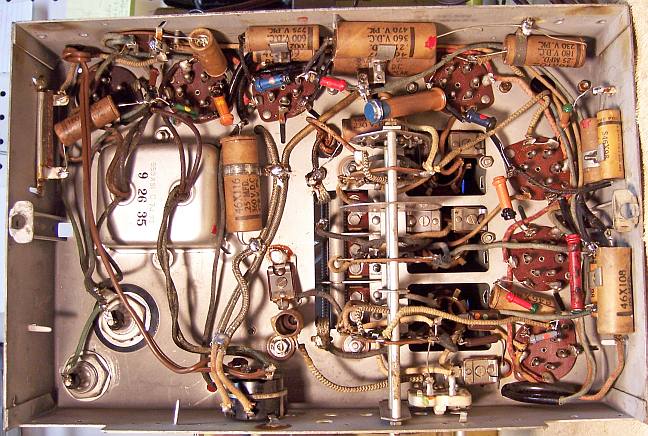
Before and After Restoration Photos
Chassis Bottom Before and After Restoration