Universal Small Cathedral Restoration
|
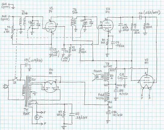
The radio is a small 4-tube TRF
circuit cathedral radio branded Universal. There is no model number
indicated. No schematic has been found. I drew a hand-drawn schematic for the radio before
starting restoration.
The radio had seen some servicing in the past. All paper
capacitors and resistors were original. The line cord and
the filter capacitor had been replaced. I decided to try to reverse these repairs and to restore the
set to its original condition to the extent possible, yet get it working. |
My
antique radio restoration logs
Condition As Found
This radio was purchased on the Antique Radio Forums Classified
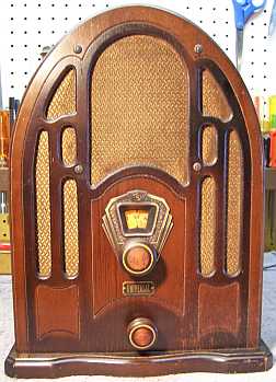
Site. The cabinet was in good condition with its original finish, but
a little faded.
The grille cloth also looked to be original. The knobs had been replaced
by the seller, but were appropriate to the radio. The manufacturer of this
radio is likely Universal Radio & Television,
but this has not been confirmed. According to The Radio
Collector's Directory and Price Guide, by Grinder, Universal Radio &
Television made radios only in 1931, including three cathedral models. The
model number of this radio is unknown, but it could be 42, since the
"4" may indicate the number of tubes. Other cathedral models
listed in Grinder start with 5
and 8 (again, could be tube count). The date of manufacture is
consistent with 1931 based on the circuit and the parts used. A
photo of this radio appears in the Stein book, listed as Universal, 1931 (it has
a different dial escutcheon).
Previous Repairs
-
Various brands of tubes were installed. Two (the globe
80
and 47) were branded "Bond" and both had an L 2 date code
(possibly 1932). One of the 224 tubes was an Arcturus blue globe
type. The other was a later 24A - obviously a replacement. But
all the tubes could be replacements.
-
All of the paper capacitors were original, and were very unique
in construction.
-
All the dogbone type resistors looked to be original, and
were all 1-watt types, even though 1/3 or 1/4 watt resistors would have
sufficed in most cases.
-
The filter capacitor most likely had been changed. The
extant capacitor was a
metal cased unit, and was consistent with the age of the radio. But
its mounting holes appeared not to be original (rather ragged, as if drilled
with a hand drill - other chassis holes were clean and obviously machine punched).
And its wire leads were rubber rather than cloth covered, like the rest of
the radio. Another example of this radio on eBay had a different
type of filter capacitor, but it did not look original either (a cardboard
cased unit with metal mounting brackets soldered to the chassis).
-
There was a cardboard cased filter capacitor tacked in
(8mfd/450 volts). This looked like a much later repair, probably mid
1930's.
-
The power cord likely had been replaced. The
replacement was a cloth covered type with an old style plug. But it
was not anchored inside the chassis, and the inner conductors were rubber or
vinyl rather than cloth. The old style plug looked to be a more modern
reproduction.
-
The grille cloth looked to be original.
-
The dial bezel appeared original, but appeared to be
originally branded EUREKA. A hole had been drilled or punched right
through the RE of EUREKA for the tuning shaft. The name was mostly hidden by the tuning
knob. The shadow under the bezel matched the bezel, and there were no
extra holes or signs that the bezel had been replaced. This could be a
small manufacturer making do with what was available in the depression era
of the early 1930's. One other known example of this radio has the
same dial. A photo of another example, as well as an example on eBay,
all had different dial bezels.
Survey
My usual restoration procedure is to first make a complete
survey of the condition of all components. The survey results guide my
restoration strategy. I never apply power to a radio before
restoration, even through a "dim bulb tester" or variac "to see
if it works". If major and unique components are defective or
missing and
cannot be restored or replaced, I may elect to sell the radio for parts rather than restore it.
I always assume that all paper and electrolytic capacitors are leaky and thus should be
replaced (I always "restuff" the original containers if possible).
Any mica capacitors are assumed OK until testing proves otherwise.
-
The power transformer was tested and was OK. The high voltage winding
indicated voltage balance on both sides of the center tap (with 20
volts applied to the primary through a Variac), and wattage draw was about 5
watts unloaded at full line voltage. A transformer having shorted
turns will normally draw excessive wattage unloaded (I use an real analog
wattmeter).
-
The output transformer was OK.
-
The speaker field and cone were OK
-
All coils were OK.
-
The pilot lamp was OK
-
Only one resistor was out of tolerance by more than 20% and would have to be
replaced.
-
One chassis screw was missing.
-
The tubes were all
good. Three of the four were globe types, which would have been
appropriate if this radio was circa 1931.
-
The set screws on the replacement knobs were too long and projected from the
knobs.
Repairs
Before starting repairs I made BEFORE photos of the chassis top and bottom. I use these photos to ensure that replacement parts and
wiring are placed as close as possible to their original positions. Some
radios are subject to problems (such as oscillation or feedback) if wiring is re-routed or
lead dress is not the same as the original. Plus, I prefer to keep
the under chassis appearance as original as possible.
All tubes were removed. The tuning capacitor and filter capacitor were removed. The chassis was
dusty, but had no rust. It was first cleaned off with an air compressor.
The chassis top and power transformer were then cleaned using GoJo (white) hand
cleaner and 00 steel wool, and then wiped clean using paper towels. The
chassis was then carefully checked for any steel wool remnants which could cause
shorts.
The power cord was replaced using a reproduction cloth covered cord available
from Antique Lamp
Company. The existing old style acorn plug was reused. Several
frayed wires were replaced, and others were insulated using shrink tubing.
The 3-lead speaker cable was hopelessly frayed. A replacement was
fabricated.
One dogbone resistor (40K 1 watt) was replaced by a NOS unit of the same type
that was in tolerance. I purchase all the NOS and used dogbone type
resistors I can find just for this purpose. The remainder of the resistors
were within 20% tolerance and were left alone.
The ST type 24A tube was replaced by a globe type 324 so that all tubes were
the same types.
Volume Control
The AC switch on the volume control was OK, but the control itself was
open. The control was a complex wire wound affair with dual tapers - there
was coarse resistance wire on both ends and fine wire in the center 50% of the
control. The control also had a minimum resistance of about 180 ohms to
provide bias for the RF amplifier at maximum volume. The resistance
was about 8K ohms. The usual repair strategy is to replace the control with a
modern 10K linear taper control with switch, or to use a 10K reverse audio taper
if one can be found, and to add a fixed resistor in series for the minimum
resistance section. But if this is done, control of volume is difficult
and most of the control is crowded on one end of the control and is not smooth.
The break was between two of the sections. The wire had originally been
welded, but the weld or the wire had broken. Nichrome wire cannot be
soldered. So I tried another approach. The wire on both sides of the
break was cleaned and sanded until shiny. A small piece of thin brass was
then inserted to bridge the break. As it turns out, the resistance element
was pressed tightly against an outer insulation layer by a center insert.
The repair worked fine, but may fail in the future. The finish resistance
was about 7K ohms (originally 8K or so).
Capacitors
| Since I did not know what the original power supply filter capacitor looked
like, the existing capacitor was restuffed with new 10mfd
450 volt capacitors. The tacked in filter capacitor was removed.
Another similar radio was found on the web with the same chassis, but
this one was branded "Paramount". Perhaps this chassis
was used on many different radios. In any case, the filter
capacitor in this radio was likely what the original capacitor looked
like. The tall cylindrical shape matched the mounting holes in my
chassis. |
 |
I
attempted to reproduce the unique paper capacitors rather than pepper the set
with new mylar capacitors. The original capacitors appeared to be a normal
paper-foil roll capacitor with attached end leads. The leads were then
wrapped around a slotted fiber board to reinforce them and to prevent them being
pulled loose. The entire assembly was then dipped in some sort of low
melting point black
wax. I suppose the purpose of the wax was to prevent moisture absorption. The
normal method of manufacture would have been to insert the foil roll in a cardboard
tube and then seal the ends with wax. Unfortunately, the wax tends to
crack with age, thus admitting moisture. None of the capacitors had any
form of identifying information, such as value or manufacturer. There
were about three different sizes used in the radio. Most originals were
too leaky to measure accurately. Based on the measurements I could do, and
circuit usage, I chose reasonable values - all at 630 volts. The values
used are documented in the hand-drawn schematic.
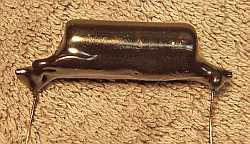
In order to reproduce these capacitors, I attached a modern film capacitor to
the original fiber board and added longer leads (Step 1 below). The assembly was then
dipped in melted rosin/wax salvaged from RCA Radiola Superheterodyne catacombs (Step 2
below).
Finally, the assembly was painted using semi-gloss enamel (Step 3 below). The
result was a little to shiny - I should have used flat black enamel paint!
Here is a photo
of an original and a reproduction capacitor:

Cabinet
The cabinet was vacuumed and then cleaned using GoJo white hand cleaner and
00 steel wool. No further treatment was needed. The knob set screws
were changed to shorter screws.
Testing and Alignment
Once the radio chassis was reassembled and the tubes installed, power was brought up
slowly using a variac in order to reform the filter capacitors and to check for
problems. The radio powered up and voltages were normal, but
there was no reception. The radio was completely dead. The problem
was traced to an open primary winding on the antenna coil. This coil had tested OK during my initial survey, but was now open. One end of the
primary winding had broken at the terminal, and was easily repaired. Movement of
the terminal during cleaning and repair had likely caused the break. Once
this was repaired, the radio was working, but badly out of alignment.
There were only two trimmers, and these were easily adjusted. The radio
worked very well for a 4-tube TRF, with only a 25 foot antenna in my basement
ceiling (and I am in a rural area). The repaired volume control worked
very well.
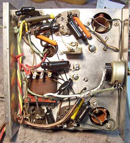
Restoration Results
Chassis Bottom Before and After Restoration