Zenith 4K402D (4-K-402D) Portable Restoration

|
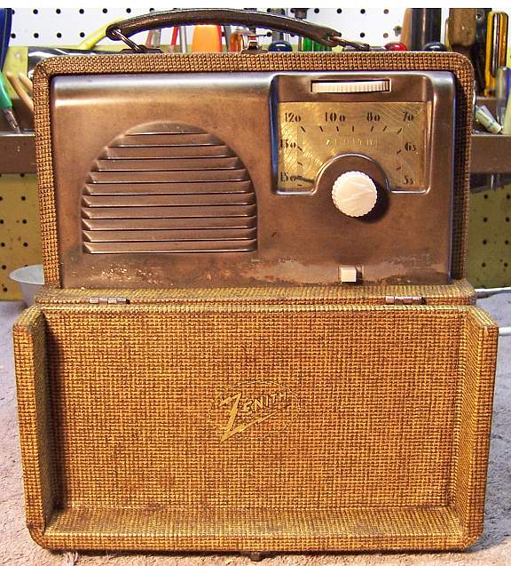
The Zenith 4K402D (4-K-402D) Portable radio is a 4-tube dry
cell battery superhet circuit portable. It receives only the
broadcast band. The combination battery delivers 1.5 volts and
90 volts. The set has a built-in loop antenna, and can also accommodate
an external antenna and ground. The schematic for the Zenith 4K402D is on-line at Nostalgia
Air.
The radio had seen no obvious servicing in the past - all of the original parts were still in place.
My restoration objective was to maintain as much originality as possible
and yet get the radio working. |
My
antique radio restoration logs
Condition As Found
This radio was purchased on eBay, where it was advertised as
"unmolested", which was certainly true. All the original parts
were still in place, including the original Zenith branded "G" type
tubes (tall tubular types). This radio, and other Zeniths of this vintage,
used rubber covered wiring, which by now has crumbling insulation
(interestingly, only certain colors!). The
battery cable had been repaired using electrical tape to prevent shorts.
One of the two brass chassis retaining plates had been replaced with a flat washer
(indicating that the chassis MAY have been removed at some point), but no parts
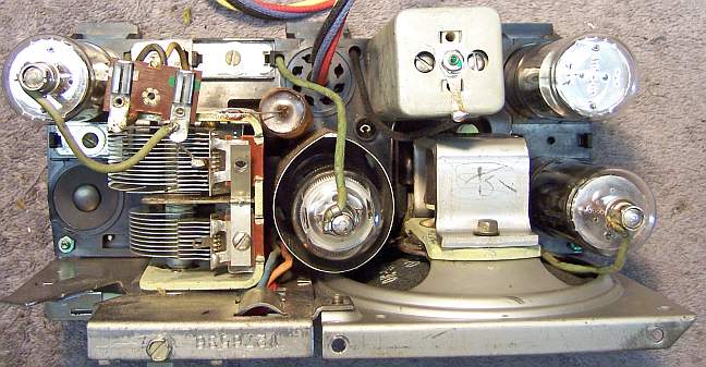
had been changed. This radio uses the infamous "upside down bakelite
chassis" which was used by Zenith for a short period of time as a cost
saving measure. The chassis itself is the same as the one used in the 6-tube AC/DC
sets such as the 6D413, but two of the tube sockets are not used - one is
blocked off, and the battery cable is routed through the keyway in the other.
Survey
My usual restoration procedure is to first make a complete
survey of the condition of all components. The survey results guide my
restoration strategy. I never apply power to a radio before
restoration. If major and unique components are defective or
missing and
cannot be restored or replaced, I may elect to sell the radio rather than restore it.
I always assume that all paper and electrolytic capacitors are leaky and thus should be
replaced (I always "restuff" the original containers if possible).
Any mica capacitors are assumed OK until testing proves otherwise.
-
The power switch was bad (it measured a high resistance) - dirty and/or oxidized contacts
were likely.
-
The speaker cone was perfect.
-
The output transformer was OK.
-
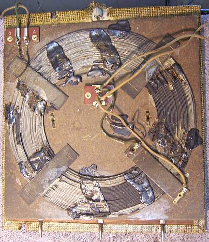
All coils and the IF transformers were OK. Some of the coils used in this
radio are quite unique in construction, and difficult if not impossible to
repair or replace. If any of them had been defective, I would have abandoned the
restoration and sold the set for parts.
-
All the tubes tested good, and were likely the originals. Two of the
grid caps were loose.
-
Most of the wiring in the radio was rubber covered and the insulation would
fall off if disturbed. Some of the wiring could be retained, but the battery
cable was a total disaster, with electrical tape repairs. The battery
cable would have to be replaced.
-
All the resistors were the original dogbone types. A few were out of
tolerance. R2 (converter screen) was +22.55%. R6 (1st AF grid)
was +37% high, but would likely work OK (I have seen 15meg used in this
position in other radios). R7 (2nd AF grid) was +22.7%. I
decided to leave ALL of these in place until the radio could be tested.
-
One brass chassis retaining plate was missing, replaced by a large flat
washer.
Repairs
Before starting repairs I made a BEFORE photo of the chassis bottom. I use these photos to ensure that replacement parts and
wiring are placed as close as possible to their original positions. Some
radios are subject to problems (such as oscillation) if wiring is re-routed or
lead dress is not the same as the original. The oscillator coil and first
IF transformer are very fragile in this radio. There are no lugs or shield
cans for either! Each is attached to the bakelite chassis and wire leads
connected directly to various points on the chassis! These leads are very
fragile, and easily damaged in handling or repair.

Before even starting the survey, ALL the capacitors were removed from the
chassis. They would eventually be restuffed anyway. And removing
them would allow more accurate measurement of the resistors' condition, since
leaky
capacitors would prevent accurate measurement of high value resistors.
Also, the capacitors often covered buried components. As
each capacitor was removed, its value, the Zenith part number, connection points, and
original lead length was documented and its position noted on a photo of the
chassis bottom. A marking tag was attached to each, referencing my notes
on its removal. All original
Zenith paper capacitors were rebuilt in their original cases using modern 630
volt axial film capacitors in order to maintain the original under-chassis
appearance. I reseal the cardboard tubes using rosin salvaged from
RCA catacombs (it melts at a low temperature and will not damage the replacement
capacitors). The 8mfd/150 electrolytic capacitor was restuffed using
a 10mfd/450 volt unit.
The tubes were removed, cleaned, and tested. Two had loose caps.
These were repaired by cleaning the projecting wire from the top of the tube,
removing the solder from the cap (until the hole was visible), reattaching the
cap with epoxy (making sure the projecting wire from the tube projects through
the hole in the cap), and after hardening, the cap is fluxed and re-soldered.
The power switch (a slide switch) was removed from the set and cleaned in my
old Heathkit electrosonic cleaner, rinsed, and dried with a heat gun. It
then worked well.
The battery cable was then removed by first removing the electrical tape and
then the battery plug. This was done so that the cable could be removed
from the set intact and could be accurately measured for the length of each
wire. The retaining knot was then untied and each wire measured for its
replacement. I used cotton covered wire (unrated size, available from RadioSupply.Com)
in the appropriate color for the replacement cable. One loop antenna
connecting lead had broken off, and was replaced. The remaining wire was
left intact (I avoided any unnecessary movement).

Once the radio chassis was reassembled and the tubes installed, power was
applied through a regulated 1.5 volt and 90 volt supply (a modified PermaPower
unit with added regulation, which has the correct battery sockets to mate with
the radio's battery plug). The radio worked, but not very well. The
alignment adjustments were way off. Also, it was noted that the set broke
into oscillation as the adjustments were peaked. The problem was isolated
to a poor ground to the second IF transformer shield. The rivets holding
the shield to its lugs were apparently corroded, and not making a good
connection. And since this radio has a bakelite chassis, the shield ground
depended on ground leads soldered to the mounting lugs. I did not wish to
remove the IF transformer and replace the rivets, since that would risk damage
and also disturb the fragile original wiring, thus forcing its replacement. So
I simply attached a ground lug to the top screw and ran a ground lead to a point
which was connected to the metal chassis and the negative A battery lead.
The set was now stable and could be aligned.
Once working well, the set suddenly failed! The output transformer
primary had decided to open up. This could be a showstopper, since the
transformer is very small and must fit in a small cavity molded into the bakelite
chassis. The transformer case was riveted to the speaker basket. I first
disconnected the wiring and removed the speaker. This is not an easy task,
since one mounting screw passes through the chassis with its nut inside the IF
amplifier tube shield! I found a small output transformer in my junk box
that appeared small enough to work. I had no idea of its impedance ratio,
but decided to simply try it and see if it worked. But that transformer
also had an open primary! I performed some surgery and found that the
leads were no longer connected to the ends of the winding. I attached new
leads and soldered them to the primary winding ends, which were fortunately
still intact. The winding then measured 506 ohms DC - the original was
about 700 ohms. I removed the shell of the replacement transformer.
One rivet retaining the original transformer to the speaker basket was ground
off using a Dremel tool. The secondary leads were unsoldered, one leg of
the frame raised enough to remove the original core and coil, and the
replacement inserted. It did fit, although somewhat smaller than the
original. The frame (and a ground lug for the voice coil lead) was
reattached to the speaker from using a 6-32 screw and nut. The speaker was
then reinstalled in the set. The original transformer had two solder
lugs. The replacement only had wire leads. I simply ran these leads
to the appropriate points in the chassis (pins 3 and 4 of the 1C5G output tube),
removing the original leads that went to the transformer. Capacitor C8
(the quality capacitor) was relocated and connected directly to the 1C5G plate
and B+. Once retested, the set worked OK. I noted no difference in
performance with the replacement transformer.
After restoration was complete, I attempted surgery on the defective
transformer. I found that one winding lead had broken loose from a
terminal. This was repaired. I did not replace the transformer, but
kept it along with the two wires removed with the radio.
Cabinet
The cabinet needed a good vacuuming inside and then cleaning on the
outside with GoJo and 00 steel wool. A replacement chassis retainer clamp
was fabricated from scrap brass.
Restoration Results
Chassis Bottom Before and After Restoration