Zenith 5R216 (5-R-216) Restoration
|
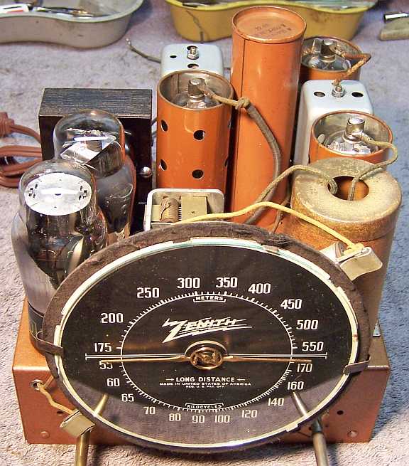
The Zenith 5R216 from 1938 is a 5-tube AC Superhet. It only receives the Broadcast band. The cabinet
is solid wood - no veneer. The schematic for the 5R216 can be found on-line at Nostalgia
Air. Any references to part numbers refer to that schematic.
The radio had seen minimal servicing in the past - all of the original parts
(except 1 tube and the AC line cord) were still in place. I decided to try to maintain the
set in its original condition to the extent possible, yet get it working. |
My
antique radio restoration logs
Condition As Found
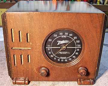
This radio was purchased on eBay. The cabinet finish,
knobs, and grille cloth were original and in very good condition. The
cabinet showed signs of finish oxidation, and was dark in places. But it
was more than acceptable to me, and certainly did not warrant refinishing.
The cord
was cut off, and the radio sold as not working (the seller powered it up with a
temporary cord and said it hummed, but no reception). As found, the
chassis was very dirty and dusty, but with minimal rust.

Previous Repairs
-
All tubes except one were the original Zenith engraved base
types with date codes consistent with the radio's manufacturing date. The 5Y4G
had been replaced, or at least was not Zenith branded.
-
The line cord had been cut off, likely because it was
unsafe. And it had been replaced more than once. There was no
line cord chassis grommet or bushing present.
-
All original wiring, resistors, and capacitors were
fortunately still in place, including the antenna and ground leads with
their label tags.
Survey
My usual restoration procedure is to first make a complete
survey of the condition of all components. The survey results guide my
restoration strategy. I never apply power to a radio before
restoration, even through a "dim bulb tester" or variac "to see
if it works". If major and unique components are defective or
missing and
cannot be restored or replaced, I may elect to sell the radio for parts rather than restore it.
I always assume that all paper and electrolytic capacitors are leaky and thus should be
replaced (I always "restuff" the original containers if possible).
Any mica capacitors are assumed OK until testing proves otherwise.
-
The output transformer had an open primary (so much for the eBay seller's claim that the
radio hummed!).
-
The power transformer was tested and was OK. The high voltage winding
indicated voltage balance on both sides of the center tap (with 20
volts applied to the primary through a Variac), and wattage draw was about 5
watts unloaded at full line voltage. A transformer having shorted
turns will normally draw excessive wattage unloaded (I use an real analog
wattmeter).
-
The speaker field and cone was OK.
-
All coils and the IF transformers were OK.
-
The pilot lamps were both burned out. Both diffusers had small holes
burned in them from lamp heat.
-
All the tubes tested good.
-
Four resistors were out of tolerance by more than 20% and would have to be
replaced. Two were normal carbon composition types (R3 1 megohm 6Q7 and 6F6 grid resistors), and two were 1/4 watt dogbone types (the 470K and
180K bias dividers, R5 and R6)
-
Two chassis bolts were missing.
Repairs
Before starting repairs I made BEFORE photos of the chassis top and bottom. I use these photos to ensure that replacement parts and
wiring are placed as close as possible to their original positions. Some
radios are subject to problems (such as oscillation) if wiring is re-routed or
lead dress is not the same as the original. Plus, I prefer to keep
the under chassis appearance as original as possible.
All tubes were removed. The tuning capacitor, dial assembly, and filter
capacitor were removed. The chassis was very dirty, but had no rust. It was first cleaned off with an air compressor. The top and sides of the chassis
were then cleaned with GoJo hand cleaner and 00 steel wool. Small bottle
brushes and a toothbrush were used in tight areas. Since the steel wool
may leave small fragments, I go over the chassis afterwards with a vacuum, a
small magnet, and masking tape.
The AC line cord stub was replaced with a new brown vinyl cord. A suitable
rubber grommet was used as a chassis bushing. I have no clue what the
original looked like. None of the wiring in the radio needed replacement,
since all wiring was cloth covered vs. rubber covered.
The pilot lamps were replaced with #44 lamps. The holes in the lamp
diffusers were
patched using small pieces of white thin plastic from an grocery store food
container and Elmer's Stiks-All glue.
Output Transformer
The original output transformer had an open primary winding. The
transformer was mounted by extensions of the frame which are passed through
slits in the mounting bracket on the side of the speaker, and then folded over
(no screws or rivets used). So any replacement transformer would have to
be close to the same dimensions. I maintain a collection of both new and
used output transformers. I also mark all these transformers with their
measured turns ratio. This is measured by connecting the primary to my HP
200A audio oscillator and driving the primary at about 12 volts at 400hz.
The secondary voltage is then measured, the turns ratio being approximately
equal to the primary voltage divided by the secondary voltage. The
impedance ratio can then be calculated by taking the square of this
ratio. In this case, the output tube is a 6F6, which needs a load
impedance of about 7000 ohms. The speaker voice coil measured 4.8 ohms DC,
or about 5.3 ohms impedance (adding 10%, usually a good estimate). I later actually measured the voice coil
impedance at 5.47 ohms at 400hz. I measure voice coil impedances by
connecting the voice coil in series with a carefully measured 5 ohm resistor to
my HP 200A audio oscillator and driving the series combination at about 1
volt. By measuring the voltage across the voice coil and the resistor, the
voice coil impedance can be calculated using simple ratios. The needed
turns ratio was thus 35.77 (Square Root of 7000/5.47).
I then started searching my output transformer stock for a single ended
transformer that was the correct size and had the correct turns ratio. I
found a transformer that was in good condition with long leads and was the
correct size to fit on the extant speaker mounting bracket, thus effecting an
almost invisible repair. But its ratio was only 27.5 vs. the needed 35.77. This
meant that the 6F6 would see a load impedance of 4126 ohms. But I really
did not have another choice, and there were no commercially available new
Hammond transformers that were compatible size wise. So I decided to
proceed and use this transformer, suspecting that I would not notice any
degradation in sound (confirmed). The transformer leads were spliced to
the existing speaker cable, insulated using heat shrink tubing and then covered
by a wrap of friction tape.
Capacitors
The original power supply filter capacitor C9-C10 was removed and restuffed.
It was a 8+14mfd @ 450 volt capacitor. It was restuffed using 10mfd and
15mfd @ 450 volt capacitors. It was very difficult to remove the contents
from the metal can. I first tried pulling out the original capacitor by
its leads - no luck. I have had some of the same types where the contents pulled without
difficulty. I then tried heating the can using a heat gun to melt the glue or
tar retaining it. Again, no luck - it would not budge. I finally had
to resort to drilling out the contents using 3/4" and 1" spade bits -
a very messy operation! I finally removed enough of the contents to allow
re-stuffing, but in the process dented the metal can in several spots when
cleaning out the contents using screwdrivers. I had an identical empty can
in my Zenith parts stock, so I decided to use that one.
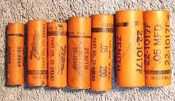
All the original Zenith paper capacitors were rebuilt in their original cases
using modern 630 volt film capacitors in order to maintain the original
under-chassis appearance. Only 7 capacitors needed rebuilding. My re-stuffing process is as follows:
- The original capacitor is removed from the radio, and the required lead
length and any spaghetti sleeving use and its length noted. I also
document which capacitor lead (outside foil) goes to which terminal.
- The low melting point wax from each end is melted and removed using an old
25 watt soldering iron.
- The original wire leads are removed, as well as any remaining wax.
The leads are normally attached to the foil roll using a low melting point
metal or solder. The heat of the soldering iron used to remove the wax
will normally release the leads also.
- While the wax is still molten, a small screwdriver is used to push out the
original paper-foil roll. In some cases, the contents comes out when the leads
are pulled out.
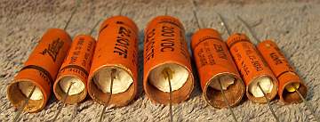
- The original cases are then cleaned out, and any wax and dirt on the
outside removed by gently heating the body over a small alcohol lamp and
wiping with a paper towel while still molten. At this point, the cases
look like this (these are from another Zenith radio):
- If the required lead length is longer than that of the replacement
capacitor, a piece of bus wire is attached before re-stuffing (the splice
being hidden inside the case).
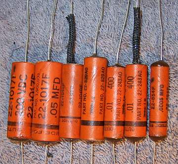
- The replacement capacitor is wrapped in a narrow strip of
paper towel in order to keep the new capacitor centered and to keep it from falling out. Here
are the finished capacitors from another Zenith before sealing the ends.
- The finished capacitor is then sealed with melted rosin (salvaged from
early RCA Superhet catacombs, and donated by or purchased from members on Antique
Radio Forums). I do NOT recoat the outside of the rebuilt
capacitors with wax (I'm not sure what was originally used - probably
beeswax).
Cabinet
The cabinet needed a good vacuuming inside and then cleaning on the
outside with GoJo and 00 steel wool. The cabinet was then waxed using
Johnson's Paste Wax. No further treatment was needed.
The front grille cloth was loose from the cabinet when received. It was stapled back to the cabinet. Felt
bumpers were added to the base. This set uses thick cardboard chassis
spacers. These were loose in the cabinet as found. They were stapled
to the base of the cabinet in their original positions (as indicated by staples
still present in the spacers, and tell tale holes in the cabinet bottom).
Testing and Alignment
Once the radio chassis was reassembled and the tubes installed, power was brought up
slowly using a variac. AC power consumption was monitored using a watt meter, and a
DVM monitored the B+. The radio powered up and the audio section worked, but
there was no reception. The B+ was much lower than expected: only about 185
volts at 110 volts AC input. And the negative bias on the 6F6 output tube
was very high - almost 28 volts. In addition, the 6A8 oscillator grid
measured +5 volts, and should have been negative if the oscillator was
running. This indicated that something was pulling down the B+ (which
would also increase the negative bias). There was no short or leakage from
B+ to ground. My DVM measured resistance of more than 40 megohms from B+
to ground. I noticed that the B+ started very high at power on, and then
rapidly decreased. This suggested that a tube was drawing too much
current. All the tubes had been tested and were good, and there were no
shorts indicated. I then started pulling tubes, beginning with the 6F6
output tube. Only a slight increase in B+ was noticed. I then pulled
the 6A8 converter, and the B+ jumped to 220 volts! I then retested the 6A8
on my Hickok 800 tube tester. Again it tested good, and there were no
shorts present. I then tested the tube for gas - BINGO!!! It was gassy, and
I then noticed that there was a blue glow inside the tube elements. I
substituted a good Zenith 6A8G tube and the radio sprang to life. It was
then aligned, which is a very simple procedure since this radio does not have
short wave. The set is very sensitive for a 5 tube set, and the tone was
OK considering it only has a 4" speaker. The replacement output
transformer worked out OK.
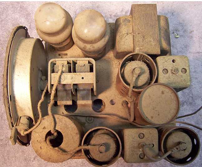
Restoration Results
Chassis Bottom Before and After Restoration