Zenith Model 5S319 (5-S-319) Restoration
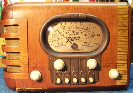 |
The Zenith model 5S319 (5-S-319) from 1939 is a small tabletop
5-tube AC superhet circuit radio.
It receives the standard broadcast band and one short wave band, and has
"automatic" or push-button tuning. The radio had seen some servicing
and restoration in the past. I
decided to try and restore the original top and bottom chassis appearance if
possible and reverse previous repairs and restorations to the extent
possible.
The schematic for the Zenith 5-S-319 can be found on Nostalgia
Air. Any part numbers will refer to numbers on that schematic. |
My
antique radio restoration logs
Previous Repairs
-
A new AC line cord and plug had been installed (the wrong
color!)
-
The original grille cloth and cardboard backer had been
replaced (the cardboard backer was likely destroyed when the original grille
cloth was replaced). The replacement cardboard looked like it was
copied from the original.
-
The speaker cone had been repaired (a hole patched).
Likely someone punched a hole in the cloth and speaker (the reason the cloth
was replaced?)
-
All the tubes were replacements, and most were incorrect: a
6X5GT was installed (should be 6X5G), a 6Y6GT output tube was installed (should be 6K6G), a 6A8GT was installed (should be
6A8G), and a 6R7 (metal tube) was installed and the Zenith gold tube shield
removed (should be 6Q7G with shield). A 6K7G was installed, but it was
not a Zenith so it likely was not original. All the replacement tubes tested
good. The 6R7 and 6Y6GT (which has a 1.2
amp filament!) were not good replacement choices.
-
The original Zenith filter capacitors had been replaced (one
replacement was a 10mfd non-polarized capacitor!)
-
The pilot lamps were type 1847 (post-war replacement for
type 47) and were good.
Survey
My usual restoration procedure is to first make a complete
survey of the condition of all components. The survey results guide my
restoration strategy. If major and unique components are defective or
missing and
cannot be restored or replaced, I may elect to sell the radio rather than restore it.
I always assume that all paper and electrolytic capacitors are leaky and thus should be
replaced (I always "restuff" the original containers if possible).
Any mica capacitors are assumed OK until testing proves otherwise. The
automatic tuning unit (push button assembly) was removed in order to gain access
to the other components. Fortunately, only three wires had to be
disconnected. I found:
-
The AC power switch was bad - dirty and/or oxidized contacts likely.
-
The rivet holding a single tie point on the side of the chassis (common
positive for the two tubular filter capacitors) had been pulled through the
mounting foot of the tie point and the tie point was floating in air.
This may have happened during the filter capacitor replacement.
-
The speaker field, output transformer, power transformer, and all RF and IF
coils and transformers were good.
-
One 470K dogbone resistor was +28% high. The remaining resistors were
within tolerance.
-
All paper/wax capacitors were the original Zeniths - none had been replaced.
-
A nut was missing on one IF transformer mounting stud, leaving a tie point
floating.
-
The gimmick capacitor (a wire connected to the oscillator tuning capacitor
and supposedly wrapped around the 6A8G grid lead) was not in place.
-
The tuning capacitor mounting grommets were bad.
-
Two knobs had chips (probably due to difficulty in removing them from the
shaft!) The set still had it original knob felts.
Repairs
All tubes and shields were removed. The tuning capacitor was then
removed for cleaning access to the chassis, and to replace the mounting grommets
(I used standard rubber grommets). I then take photos of the chassis
bottom so that routing of wiring and component placement can be restored.
Lead dress is often critical in radios. When I replace a component, I
always remove the original part completely from a terminal. Other
components connected at the terminal are protected from heat using old medical
clamps. Excess solder is then removed using a solder sucker in order to
expose terminal holes for reattachment of the rebuilt or replaced component.
The replacement filter capacitors were removed. The rivet on the side
of the chassis which had pulled through a single tie point was removed and
replaced with a Zenith type 6-32 hex head screw and nut, which matched other
screws on the chassis.
The volume control switch was flooded with Big Bath cleaner and cycled many
times. The switch eventually worked. The push-button tuning contacts
were badly corroded. The contact springs were cleaned with DeOxit and
lacquer thinner. The fixed contacts were eventually cleaned with 600-grit
emory paper, followed by lacquer thinner.
The top of the chassis was cleaned with GoJo hand cleaner and 00 steel
wool. The tuning capacitor was cleaned in an old Heathkit ultrasonic
cleaner with dilute ammonia. After drying, the bearings were lubed with
Lithium grease.
The line cord was replaced with a NOS brown vinyl cord (at least it is safe
and the correct color).
The grille cloth was replaced with a modern reproduction. The
replacement was similar to the original. It was attached to the
replacement cardboard backer. The knobs (two of which had chips) were left
as is. I was unable to find a source for originals (for split
shafts). Reproductions are available, but ALL knobs must be replaced,
since otherwise the color will not match.
Resistors and Capacitors
All paper capacitors were rebuilt in their original cases
using modern 630 volt film capacitors in order to maintain the original
under-chassis appearance. I reseal the cardboard tubes using rosin
salvaged from RCA catacombs (it melts at a low temperature and will not damage
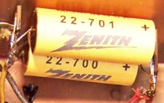
the replacement capacitors. The original Zenith filter capacitors had
been replaced. I found an original Zenith electrolytic capacitor in my junk
capacitor box and fabricated reproduction covers having a similar color, the
Zenith logo (found on the web) and the correct original part numbers and values.
These covers were then attached to two large tubular paper capacitor cardboard
tubes which were gutted and stuffed with new 10mfd 450 volt electrolytics.
I was unsuccessful in finding out what the originals looked like, but the
reproduction covers look better than just using modern capacitors with no covers
(and they do have the correct part numbers).
The one dogbone resistor out of tolerance was replaced by a NOS dogbone
resistor that had drifted to near the correct value. It was repainted
using hobby paint to the correct color codes. While this resistor may
continue to drift, so will the others in the set. I wished to maintain the
original above and below chassis appearance.
Testing and Alignment
Once the radio was reassembled and the tubes installed, power was brought up
slowly using a variac. AC power consumption was monitored using a watt meter, and a
DVM monitored the B+. The radio came alive immediately and worked.
The set was then aligned - no surprises. The push buttons were
adjusted to local stations, after I used a signal generator to find the tuning
range of each button.
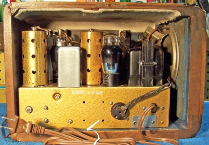
Restoration Results
In the BEFORE chassis photo, the push-button tuning unit and tuning capacitor
have been removed for access.
|
Chassis Before Restoration |
Chassis After Restoration |
 |
 |