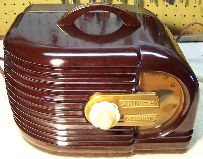
Zenith 6D315 (6-D-315) Restoration
 |
The Zenith 6D315 "Wavemagnet" from 1939 is a 6-tube AC/DC Superhet
circuit radio that
receives only the broadcast band. The radio had been serviced in the past but most
of the original
parts were still in place. I
decided to try and reverse all prior servicing and restore the original chassis appearance if
possible.
The schematic and a parts list for the radio can be found on Nostalgia
Air. Any part number references in the text below reference that
schematic. |
My
antique radio restoration logs
Overview
This model Zenith is very unusual looking, IMHO! The
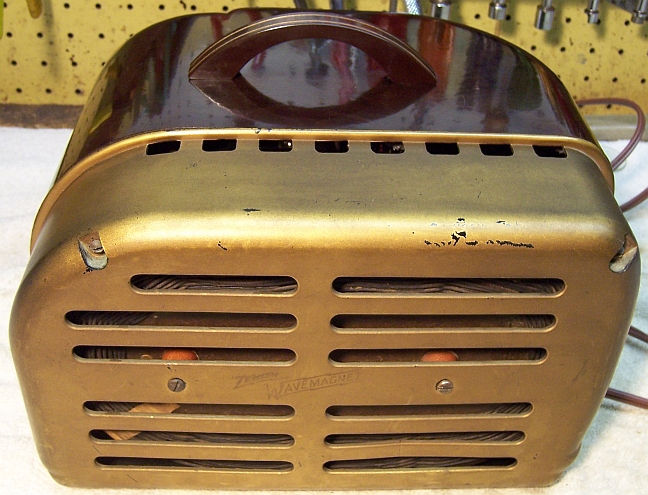
Wavemagnet back appears to have been just tacked on. There are very
similar examples of this radio with the same cabinet but WITHOUT the loop
antenna or Wavemagnet back (they have a plain cardboard back). Those
radios use an almost identical chassis that uses an antenna coil and thus
requires an external antenna (6D311).
The radio was purchased on eBay. Externally it appeared to be all
original, complete and in excellent condition. The line cord was original and
almost totally without insulation! The radio had not been plugged in or tested.
There were no cracks or breaks in the front part of the cabinet, and only one
small crack/break in one of the ribs of the Wavemagnet back cover.
The chassis is
small and quite compact, and access to parts is limited and difficult. For
example, to replace the tuning capacitor mounting grommets, one must disconnect
several leads from the fragile oscillator coil, straighten out its mounting
tabs, and move it out of the way in order to remove the tuning capacitor
mounting hardware and the grommet remnants. Otherwise, there is risk of
damaging the coil.
There were many differences between the radio's actual circuit and available
schematics. This made servicing more difficult than usual. For
example, in the
published schematics, R9 was 60 ohms and R10 was 50 ohms (Micamold wire wound
types). In my radio, R9 was 90 ohms and R10 was 12 ohms! Also, R5 and R6
had not been installed. It appeared that these changes reduced the parts
count by two yet provided the same bias voltage for the 6Q7 and 25L6 tubes. In
addition, the Wavemagnet antenna was NOT shielded as indicated in the schematic (and
other examples of this radio I have seen), even
though the ground connection socket and capacitor C14 were present. There
was no evidence that the shield had ever been installed. Perhaps this was
another cost reduction measure.
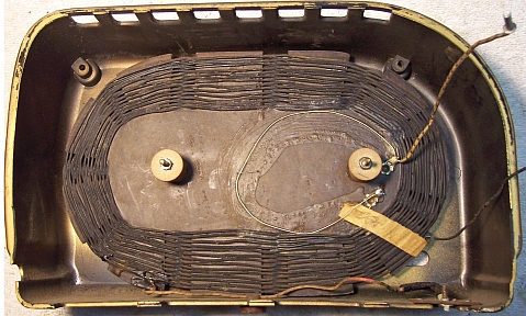
Here is a view inside the Wavemagnet back cover. Notice
the loop of wire glued to the Wavemagnet. It appears that about one turn was
electrically either added or removed from the loop. This loop appears original,
but it is difficult to tell. The loop is on top of the original tape that
secures the start of the winding, and is both glued and stapled in place..
Prior Servicing
I always attempt to avoid purchasing radios that have been
"restored" by collectors or flippers, and am looking for either all
original examples or those which have been "lightly serviced" in the
distant past by radio service shops. In this example, many parts had been
replaced long ago - likely by a service shop and not a recent restoration.
-
Both filter capacitors C11 and C12 had been replaced by
similar tubular units by Sprague ("Atoms") or Pyramid. The originals had been removed.
Both replacements were older vintage parts.
-
Four paper-wax capacitors had been replaced. All
replacements were either Solar or Pyramid branded but were different types.
All replacements were older vintage parts. To date I have not found a
reference for the date codes of the replacements.
-
All resistors appeared to be original.
-
The ballast tube 100-70 was an original Zenith (and
fortunately GOOD). All remaining tubes had been replaced. The
6A8G, 25Z6G, and 25L6G had been replaced with GT type tubes. The 6K7G
and 6Q7G were good.
Cleaning
The chassis was dusty, but not rusty. All tubes and the tube
shield were removed. The dust was vacuumed off, top and bottom. After removal of
major parts for servicing (dial, tuning capacitor, speaker) the top of the
chassis was cleaned using GoJo hand cleaner and 00 steel wool. The chassis
was then vacuumed once again to remove any possible steel wool fragments.
Survey
In Zenith schematics, all
resistors and capacitors having the same value have the same part number call
out. So for example, there may be multiple R2's or C4's on the schematic.
Before I start work on the chassis I annotate the schematic so that all parts
have unique identifiers. I usually add an alphabetic suffix, so that the
part numbers are thus R1A, R1B, etc. I then annotate the chassis photo with
these unique part numbers with a red felt-tip pen. I then removed all
non-original capacitors, documenting their locations
and connections.
-
Except for the ballast tube, all tubes had been replaced.
The replacement 6Q7G and 6K7G tubes were the correct types and were good. One half of the
25Z6GT was bad! The 25L6GT was OK. The replacement 6A8GT was very
weak. The ballast tube was OK.
-
The speaker field coil and cone were OK.
-
The output transformer was OK, although the primary DC
resistance was lower (100 ohms) than I have observed in similar
radios.
-
The oscillator coil was OK
-
The IF transformers were OK.
-
Both 47K resistors (R1) were out of tolerance. Three dogbone type
resistors were also out of tolerance.
-
Wire wound resistor R9 (90 ohms) measured 130 ohms.
R10 (12 ohms) was OK.
-
Five paper-wax capacitors had been replaced. All
replacements were Solar Sealdtite brand.
-
The B+ bypass capacitor C2 (original Zenith part) was
shorted!
-
The volume control was OK, but the attached switch did not
work.
-
The dial lamp was OK.
-
The line cord was shot.
-
The tuning capacitor mounting grommets were shot.
Restoration Strategy
Since almost all of the original parts were still in place I decided to try and
maintain the
original chassis appearance to the extent possible. All
original capacitors would be rebuilt in their original cases (restuffed). Any parts replaced in
servicing would be replaced with original parts if available. Any out of tolerance
resistors would be replaced with the same types if available. When I replace a component, I
always remove the original part completely from a terminal. Other good components connected at the terminal are protected from heat using old medical
clamps (hemostats). Excess solder is then removed using a solder sucker in order to
expose terminal holes for reattachment of the rebuilt or replaced component.
I assume that all paper and electrolytic capacitors are leaky and thus should be
replaced (I always "restuff" the original components if possible). I
do not replace mica capacitors, but may test them in place if possible (usually
this requires disconnecting one end of the capacitor).
Repairs
Resistors
The radio used older style "dogbone" type
resistor as well as 20% tolerance carbon composition resistors. Both instances of R1
(47K) were replaced by similar 1/2 watt units, although I was forced to use 10%
or 5% replacements, since 20% units are no longer available. In order to replace
a "dogbone" resistor, I keep a stock of NOS and used "dogbone" resistors, and buy all I can
on eBay and at radio swap meets (when reasonably priced)! Of course, most of these resistors, even NOS resistors, have also
drifted in value and no longer have their marked values. My solution to
this problem is to
find a replacement resistor of the correct value and size as measured (ignoring the
markings), and then repaint it to the needed value codes using enamel hobby
paint! In the case of R2 (10K) I found an NOS unit in my stock that was
in tolerance (measured 10.56k). The 6Q7 grid resistor (15meg vs. the 1meg documented in
the schematic) was replaced by a 10meg "dogbone" resistor that
measured 14.42meg. It was repainted as 15meg (only the end color had to be
changed).
R9 (90 ohms, wire wound) was out of tolerance, and its value is
critical, being a component of the bias supply for the 25L6 and 6Q7 tubes.
I wired in a 300 ohm 1/2 watt carbon composition resistor, enclosed in a piece
of black spaghetti tubing, in parallel to bring its value back to 90 ohms.
The fix is almost invisible, since it was buried among components and wiring
around the 6Q7G socket. A replacement modern power resistor would have
been very visible since R9 and R10 are on top of the chassis.
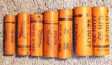
Wax/Paper Capacitors
All of the original Zenith paper capacitors were rebuilt in their original cases
using modern 630 volt film capacitors in order to maintain the original
under-chassis appearance. In the case of the four Zenith capacitors
that had been replaced, I found suitable original Zenith capacitors in my stock
of duds. All the Zenith duds had the correct values and voltage ratings,
but only two had the same Zenith part numbers as documented in the schematic
parts list..
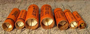
My re-stuffing process is as follows:
- The original capacitor is removed from the radio, and the required lead
length and any spaghetti sleeving use noted.
- The low melting point wax from each end is melted and removed using an old
25 watt soldering iron.
- The original wire leads are removed, as well as any remaining wax.
- While the wax is still molten, a small screwdriver is used to push out the
original paper-foil roll. In some cases, the contents comes out when the leads
are pulled out.
- The original cases are then cleaned out, and any wax and dirt on the
outside removed by gently heating the body over a small alcohol lamp and
wiping with a paper towel while still molten. At this point, the cases
look like this (these examples are from a different Zenith radio I
restored):
- If the required lead length is longer than that of the replacement
capacitor, a piece of bus wire is attached before restuffing.
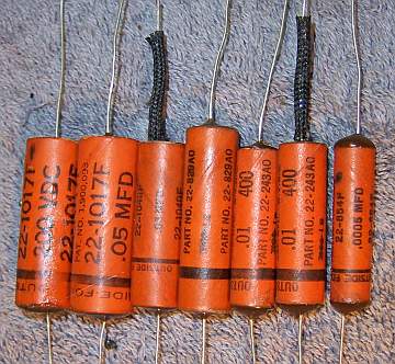
- The replacement capacitor is wrapped in a narrow strip of
paper towel in order to keep the new capacitor centered and to keep it from falling out. Here
are the finished capacitors before sealing the ends.
- The finished capacitor is then sealed with melted rosin (salvaged from
early RCA Superhet catacombs, and donated by or purchased from members on Antique
Radio Forums). I do NOT recoat the outside of the rebuilt
capacitors with wax (I'm not sure what was originally used - probably
beeswax).
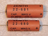
Filter Capacitors
The original tubular filter capacitors C11 and C12 had been
removed and replaced with vintage Sprague or Pyramid tubular capacitors. Rather than just tacking in new modern electrolytics, I
decided to attempt to reproduce the originals. But I have never seen a
photo of the originals (I did notice an unanswered Want To Buy advertisement on
the Antique Radio Forum Classifieds for these exact parts, for
restuffing). I did have a Zenith dud capacitor in my stock, but it was a
different value and part number. But I was able to use it as a model to
fabricate reproductions with the same approximate fonts, colors, and labeling.
I found some Aerovox ceramic tube type paper capacitors in my dud
capacitor stock that were the approximate size needed. These were cleaned
out and stuffed with modern parts. C11 (40mfd) was restuffed with a
47mfd@160 volt electrolytic. C12 (16mfd) was restuffed with a 15mfd@350
volt electrolytic. The new parts were wrapped in strips cut from paper
towels in order to center them in the ceramic tubes. The ends of the tubes
were then sealed using melted rosin salvaged from servicing RCA Radiola Superhet
catacombs.
A paper label was fabricated using MSWord. It
contained the Zenith part number, capacity and voltage. The label was wrapped
around the ceramic tube and secured with GC Service Cement. Here are the
reproduced capacitors:
Other Repairs
The line cord was replaced by a modern brown vinyl cord. The original
plug found on the radio was re-used (it was likely NOT original).
The original 6A8GT (very weak) was replaced by the correct type 6A8G.
Correct G type tubes were installed for the 25L6GT and 25Z6GT.
The tuning capacitor mounting grommets were replaced by 5/16" vinyl
grommets from Antique Electronic Supply (P-G516).
Testing and Alignment
Once the radio had been reassembled and the tubes and tube shield installed,
the radio was powered up using a fused Variac. The radio came alive and
actually worked. The set was then aligned. The adjustments were way
off. The only alignment complexity was that if the second IF transformer
was peaked at maximum volume, the set would break into oscillation. I have
observed this in other radios, and it may have been due to changes in lead dress
or component placement (since it had been serviced before - perhaps many times).
The radio worked well and sounded good, although there was some tunable hum
(modulation hum) on some stations. I have read that in most cases, this is
caused by interference from various electronic devices around the house.
Elimination of the Wavemagnet shield could have contributed to this
effect. I have notice that Zeniths with shielded Wavemagnet antennas tend
to be much quieter than those without.
Cabinet
The Wavemagnet rear cover was cleaned inside and outside with soap and water after
removal of the loop antenna assembly. The the bakelite front of the cabinet was cleaned using GoJo (white)
hand cleaner and 00 steel wool, followed by a coat of Johnson's Wax. The knobs
were cleaned in an ultrasonic cleaner using dilute ammonia.
Restoration Results
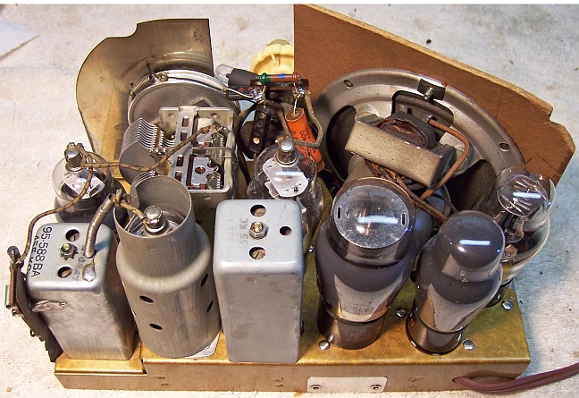
Chassis Before Restoration
|
 |
Chassis After Restoration
|
 |