Zenith 6D525 (6-D-525) Restoration
|
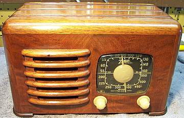
The Zenith 6D525 from 1941 is a
6-tube AC/DC Superhet with an untuned RF amplifier stage and Wavemagnet
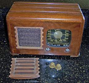
loop antenna. It only receives the Broadcast band. The cabinet
is solid walnut, and affectionately known to some collectors as "the
toaster" due to the slots in the top and sides. The schematic for the
6D525 can be found on-line at Nostalgia
Air. Any references to part numbers refer to that schematic.
The radio had seen minimal servicing in the past - all of the original parts
(except tubes) were still in place. I decided to try to maintain the
set in its original condition to the extent possible, yet get it working. |
My
antique radio restoration logs
Condition As Found
This radio was purchased on eBay. The cabinet finish,
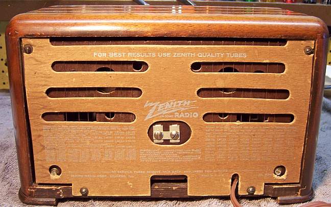
knobs, and grille cloth were original and in excellent condition. The cord
was cut off, and the radio sold as not working. The often missing back
cover was present, but the spacers between the chassis and Wavemagnet antenna
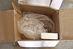
were missing. Unfortunately, the seller did not properly pack the radio
for shipment, and there was shipment damage. Here is what the radio looked like
when received, and the packing box. Only a single layer of small bubble
wrap was used for protection, and also the chassis bolts were missing, which
allowed the radio chassis to move freely inside the cabinet. Fortunately,
the damage was not serious and was repaired with no repairs visible.
Previous Repairs
-
All but two tubes were the original Zenith engraved base
types with date codes consistent with a 1940 manufacturing date. The
35L6G and 35Z5G tubes had been replaced with GT types.
-
The line cord had been cut off, likely because it was
unsafe.
-
The wooden spacers between the chassis and Wavemagnet
antenna were missing. Likely these were removed when the tubes were
replaced.
-
All original wiring, resistors, and capacitors were
fortunately still in place.
Survey
My usual restoration procedure is to first make a complete
survey of the condition of all components. The survey results guide my
restoration strategy. I never apply power to a radio before
restoration, even through a "dim bulb tester" or variac "to see
if it works". If major and unique components are defective or
missing and
cannot be restored or replaced, I may elect to sell the radio for parts rather than restore it.
I always assume that all paper and electrolytic capacitors are leaky and thus should be
replaced (I always "restuff" the original containers if possible).
Any mica capacitors are assumed OK until testing proves otherwise.
-
The AC power switch was bad (it measured a high resistance) - dirty and/or oxidized contacts
were likely. It responded to a shot of Big Bath cleaner followed by
repeated cycling and then
worked correctly. The volume control was also difficult to turn.
It responded to light oil on the bushing and the Big Bath spray used to clean the AC
switch, then moved freely.
-
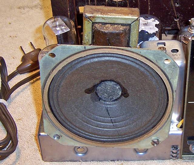
The speaker cone had a repairable tear, perhaps damaged in shipment.
-
The output transformer was OK.
-
All coils and the IF transformers were OK.
-
The pilot lamp was OK.
-
All the tubes tested good. This was great since many were the
originals and some of them are hard to find (12J7G, 12K7GT, 12SA7G).
The 35Z5G and 35L6G had been replaced with GT types.
-
Some of the wiring in the radio was rubber covered and the insulation was falling
off. All of this damaged wiring would have to be replaced.
-
All the original resistors were probably close enough to work, although some were
more than 20% out of tolerance. All resistors were either wire wound
or dogbone types, so I did not want to replace one unless absolutely
necessary.
-
The dial cord was off its pulley, and the spring had been stretched.
-
The chassis bolts were missing.
Repairs
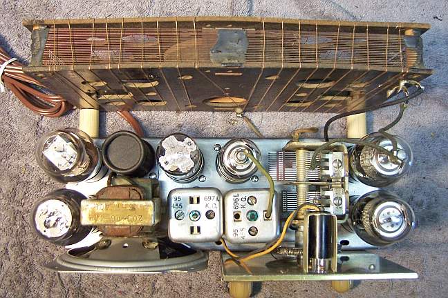
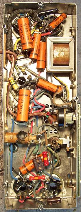
Before starting repairs I made BEFORE photos of the chassis top and bottom. I use these photos to ensure that replacement parts and
wiring are placed as close as possible to their original positions. Some
radios are subject to problems (such as oscillation) if wiring is re-routed or
lead dress is not the same as the original.
All tubes were removed. The chassis was very clean, with no rust - just
very dusty. It was first cleaned off with an air compressor. The top and sides of the chassis
were then cleaned with GoJo hand cleaner and a tooth brush.
The AC line cord stub was replaced with a new vinyl cord. Some of the
rubber covered wiring was disturbed when components were replaced, and
insulation would fall off. This wiring was replaced. I always use "unrated"
type cloth covered wire available from RadioSupply.Com
(their 600 volt rated wire is not appropriate for radio restoration). I
have not found a closer replacement for the old Zenith #22 gauge rubber covered
solid wire.
The dial cable spring was straightened up as much as possible, and the original dial cord
reinstalled. It was not obvious how the cable was originally secured to the
tuning capacitor pulley. There were a couple of small holes in the pulley
where perhaps tabs projected to engage the spring. But the tabs had broken
off. So I used a piece of thin buss wire to secure the spring to the
pulley - almost invisible.
The missing Wavemagnet antenna spacers were fabricated from 5/8" wooden
dowel stock. The center hole was drilled using my small Unimat
lathe. The exact length of the spacers was unknown, and queries on Antique
Radio Forums as well as the rec.antiques.radio+phono newsgroup did not yield
an answer. But looking at available photos of this model from the back, with the
back cover in place, gave me some idea of the location of the Wavemagnet antenna in
relation to the back cover. I finally settled on a length of
15/16". The diameter was also unknown, but there were some
indications on the chassis that gave me a clue as to the original diameter.
NOTE: Later I acquired another example of this radio that had its original
spacers intact. They were made of laminated cardboard rather than
wood. Their length was just over 15/16" and diameter was just over
5/8". So my guesses were close!
I found a good Zenith branded 35L6G tube in my stock of tubes. It had a
"1" date code (1941?). I was able to purchase a good Zenith 35Z5G
tube from a member on the rec.antiques.radio+phono newsgroup.
Capacitors
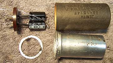
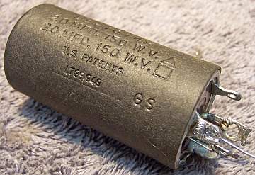
The original power supply filter capacitor C7-C8 was removed and restuffed.
It was a 20+20mfd @ 150 volt FP twist tab type capacitor. It was restuffed using two
22mfd 160 volt axial capacitors. The chassis is very compact, and there is
hardly any room to install tubular capacitors under the chassis. My
procedure for restuffing FP type can capacitors is as follows (there are many
discussions and examples with photos on Antique
Radio Forums):
- Remove the cardboard cover. In this case, it pulled off without
difficulty. Sometimes I must use a heat gun to release the glue or tar
holding it to the can.
- Uncrimp the bottom using a small screwdriver and diagonal cutters (try to
minimize damage to the outside of the can)
- Remove the mounting ring, the terminal board and the gasket behind,
cutting the aluminum leads to the capacitor body to free up the terminal
board.
- Remove the can contents using a heat gun to release the tar, followed by a
thorough cleaning using mineral spirits. In this case, the foil roll
could be removed without heating, and the remaining tar removed by
mechanical means.
- Connect the replacement capacitor leads to the original terminals by
drilling small holes through the terminal board close to the terminals,
passing the leads through, and soldering them to the terminals on the
outside. The common ground lead is passed through a small hole drilled near
one of the capacitor ground/mounting tabs. This lead is not soldered
to the ground lug until after the capacitor is secured in the chassis
mounting wafer (otherwise the solder would prevent the lug easily passing
through the hole in the mounting wafer or could damage the wafer - ASK ME
HOW I KNOW THAT).
- Reinstall the terminal board and mounting ring and restore the crimp
around the base.
- Reinstall the cardboard cover (it was not glued - just held by friction).
The cover hides any signs of the bottom crimp being disturbed. Be
aware that the capacitor body is electrically HOT (connected to one side of
the AC line), so the cover is an important safety
feature. The chassis itself is isolated from the AC line by a
capacitor.
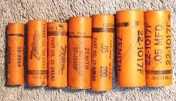
All the original Zenith paper capacitors were rebuilt in their original cases
using modern 630 volt film capacitors in order to maintain the original
under-chassis appearance. My re-stuffing process is as follows:
- The original capacitor is removed from the radio, and the required lead
length and any spaghetti sleeving use noted.
- The low melting point wax from each end is melted and removed using an old
25 watt soldering iron.
- The original wire leads are removed, as well as any remaining wax.
- While the wax is still molten, a small screwdriver is used to push out the
original paper-foil roll. In some cases, the contents comes out when the leads
are pulled out.
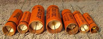
- The original cases are then cleaned out, and any wax and dirt on the
outside removed by gently heating the body over a small alcohol lamp and
wiping with a paper towel while still molten. At this point, the cases
look like this:
- If the required lead length is longer than that of the replacement
capacitor, a piece of bus wire is attached before restuffing.
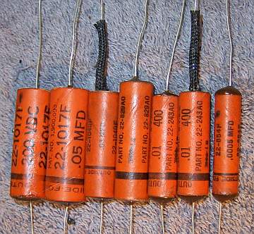
- The replacement capacitor is wrapped in a narrow strip of
paper towel in order to keep the new capacitor centered and to keep it from falling out. Here
are the finished capacitors before sealing the ends.
- One capacitor, C5 was a challenge. It was a 500pf 600 volt
capacitor. There was not enough room in the original case for a silver
mica or ceramic disc capacitor rated at 600 volts. So I used two
0.001mfd 630 volt capacitors in series. There was just enough room for
two capacitors placed end to end (but only if a certain brand of capacitor
was used - some commonly available film capacitors are too large for this
application).

- The finished capacitor is then sealed with melted rosin (salvaged from
early RCA Superhet catacombs, and donated by or purchased from members on Antique
Radio Forums). I do NOT recoat the outside of the rebuilt
capacitors with wax (I'm not sure what was originally used - probably
beeswax).
Cabinet
The cabinet needed a good vacuuming inside and then cleaning on the
outside with GoJo and 00 steel wool. No further treatment was needed.
The dial cover was loose from the cabinet when received, due to shipping
damage. It was stapled back to the cabinet. The wooden grille cover
was glued back to the cabinet. The repairs are invisible.
Fortunately, the knobs were not damaged in transit!
Testing and Alignment
Once the radio chassis was reassembled and the tubes installed, power was brought up
slowly using a variac. AC power consumption was monitored using a watt meter, and a
DVM monitored the B+. The radio came to life immediately and worked
well. The radio was then aligned. There are no alignment instructions in Nostalgia
Air that I could find. Instruction are in Riders Volume 12, Zenith
page 12-9. Alignment is very simple, consisting of the IF transformers
(peak at 455kc), wave trap (minimum output at 455kc), and antenna (1400kc) and oscillator
(1600kc) trimmers. For the IF and wave trap alignment, the signal
generator is connected to the grid cap of the 12J7G RF amplifier. For the
oscillator and antenna adjustments, the output of the signal generator is fed
into a 1-2 turn loop of wire placed close to the Wavemagnet antenna.
Restoration Results
Chassis Bottom Before and After Restoration