Zenith 6S322 (6-S-322) Restoration
 |
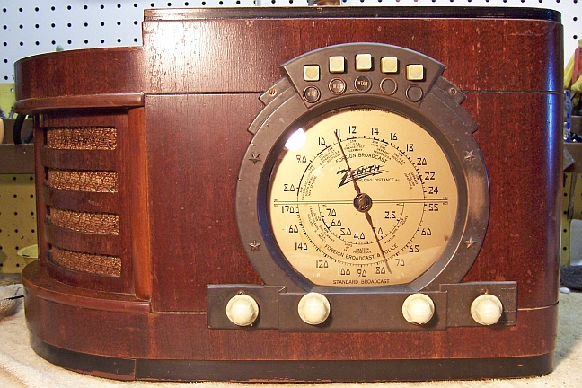
The Zenith model 6S322 (6-S-322) "Stars and
Stripes" from 1939 is a tabletop
6-tube AC superhet circuit radio.
It receives the standard broadcast band and two short wave bands, and has
"automatic" or push-button tuning. This radio also
featured flywheel tuning, which is rare except in "deep chassis"
Zeniths. The radio had seen
minimal servicing in the past. I
decided to reverse previous repairs to the extent
possible.
The schematic for the Zenith 6S322 Chassis 5651 can be found on Nostalgia
Air. Any part numbers mentioned will refer to numbers on that schematic. |
My antique radio
restoration logs
Preparation for Service
-
All tubes and shields were removed.
-
Dust was blown off using an air compressor
-
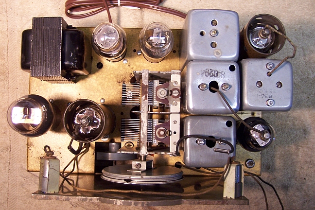
I then took "before" photos of the chassis so that routing of wiring and component placement can be restored.
Lead dress is often critical in radios.
-
The dial assembly, dial drive cable and dial pointer were removed.
-
The tuning capacitor was then removed in order to renew the
mounting grommets and for cleaning and lubrication.
Previous Repairs
-
A replacement AC line cord and plug had been installed
(white)
-
Two tubular type replacement filter capacitors for C20
and C21 had been
installed (similar type to the originals, but not clamp mounted).
-
One original Zenith wax paper capacitor had been replaced -
C15. The remainder were
all original.
-
All resistors were original.
-
The original Zenith first IF transformer had been replaced
by a newer, smaller unit.
-
Some of the tubes may have been replaced. The
6F5G, 6F6G, and 6K7G were Zenith branded, and likely original. The
remainder were Tung-Sol branded. I assume that these were
replacements, since it is my understanding that Zenith radios were
originally shipped with Zenith branded tubes. All the tubes were the
correct G types.
-
One automatic tuning contact spring apparently had broken and had been
repaired by soldering the parts together.
-
The dial drive cable had been replaced by a piece of string, and the tension
spring was missing.

Survey
My usual restoration procedure is to first make a complete
survey of the condition of all components. The survey results guide my
restoration strategy. If major and unique components are defective or
missing and
cannot be restored or replaced, I may elect to sell the radio rather than restore it.
I always assume that all paper and electrolytic capacitors are leaky and thus should be
replaced (I always "restuff" the original containers if possible).
Any mica capacitors are assumed OK until testing proves otherwise. I found:
-
The speaker field and output transformer were OK.
-
The power transformer was OK. This was tested by pulling all tubes,
and applying power through a fused variac and watt meter. I check for
balance on the high voltage winding halves, as well as correct filament
voltage. I also check for leakage between the primary and ground, as
well as the high voltage to ground. Finally, I check for full voltage
wattage. I should be very low. In this case, it was only about 5
watts.
-
All tubes were good.
-
The Z-G antenna link was missing. The A antenna lug was not firmly
attached to the fiber strip.
-
One chassis bolt was missing.
-
One knob had a chip missing on the edge, likely caused when it was removed
for prior servicing (these knobs can be VERY difficult to remove without
damage).
-
The broadcast band primary of the antenna coil (part S-6266)
was open. The short wave primary was OK, and all other coils and
transformers were OK (the first IF transformer had been replaced).
-
One tip plug that connects to the automatic tuning unit was missing.
-
One automatic tuning adjustment screw had the head broken off due to the
screw being frozen. In an attempt to turn the adjustment screw (before
the hex head sheared off), the tuning coil apparently rotated, breaking the
fine lead wires on the coil.
-
Seven resistors were out of tolerance. The Candohm metal resistor
measured 122.2/28.3/295.2 ohms, vs. specs of 120/23/290 - slightly
high. The resistances were also stable when the terminals were moved,
so I decided to use the original. It is only used for bias voltage,
and is not exposed to high voltages.
-
One pilot lamp was burned out.
Repairs
Before starting repairs, I had to deal with the replacement first IF
transformer and the open antenna coil. If these parts could not be
replaced with Zenith originals, I may have elected not to keep the radio and
wait for a better example. The antenna coil was removed from the radio and
the coil removed from the shield can. The damage was obvious. The
broadcast primary winding (bank wound) was completely loose in the can, and
showed signs of burning. The wax that normally retained the coil in place
had melted. So apparently some voltage had been fed into the
antenna. Perhaps the antenna fell on a power line. The damage did
not appear to have been caused by lightning, since it took some time for the wax to
melt. The short wave primary coil (in series with the broadcast band coil)
amazingly was not damaged. My choices were thus:
- Obtain a replacement part (perhaps from Play
Things Of Past)
- Find a parts chassis
- Try and fabricate a replacement coil, without knowing how many turns of
wire to use.
I did have a Zenith parts chassis, model 6S342 in stock. That radio had
identical band coverage, the same converter tube (6A8), and the same number of
plates on the tuning capacitor. But the part number was not the same as in
the 6S322. I removed the coil from the parts chassis and examined
it. It looked identical. So I decided to replace my defective coil
from the parts chassis and see how well it worked. If it did not work, I
would then try to rewind the primary coil or find a part chassis.
The first IF transformer on the 6S342 parts chassis looked correct for my
chassis - it had the same mounting centers as well as the 6K7G grid cap lead. The 6S342 used the same converter (6A8)
and IF amplifier (6K7) tubes, and the IF frequency was the same on both
radios. But again, the part numbers were not the same. The DC coil
resistances were slightly different (comparing the replacement transformer
primary resistance with
the original second IF transformer primary resistance). So I decided to install the
replacement from the 6S342 parts chassis and see how well it worked after
alignment.
The 6S342 parts chassis also provided the missing pin plug for the lead going
to the automatic tuning unit. But alas, the 6S342 automatic tuning unit
could not provide a replacement for the damaged coil and adjustment screw I
needed.
So having a strategy for replacing the missing original parts, I decided to
proceed with the restoration.
The top of the chassis and remaining top chassis parts were then cleaned with GoJo hand cleaner and 00 steel
wool. After cleaning, the chassis is carefully inspected for steel
wool fragments. It is important to keep steel wool away from the tuning
capacitor (it had already been removed). The tuning capacitor was cleaned
in my old Heathkit ultrasonic cleaner, followed by soap, water, and
toothbrushes. The unit was then dried and bearings lubricated using
distributor cam lubricant (similar to the original grease used).
When I replace a component, I
always remove the original part completely from a terminal. Other
components connected at the terminal are protected from heat using old medical
clamps. Excess solder is then removed using a solder sucker in order to
expose terminal holes for reattachment of the rebuilt or replaced component.
The automatic tuning contact springs and contacts were cleaned with lacquer thinner
on a pipe cleaner followed by DeOxit and then more
lacquer thinner and a pipe cleaner. But corrosion remained. So
I then used a Dremel tool with a wire brush attachment to clean the contacts and
contact springs as well as possible. The fourth spring had been repaired
by soldering. I was never able to get reliable contact between that spring
and the contacts - the contact springs are almost impossible to adjust due to
restricted access. The coil and adjustment for the fifth button had been
destroyed when the adjustment screw (or slug) seized up and was broken
off. So I wound up with only 3 automatic tuning buttons that
worked.
Resistors and Capacitors
Seven original resistors were out of tolerance. One was a dogbone type
(R4, 33K, 1 watt). The remainder were normal 1/2 watt carbon composition
types. For R4, I found an NOS 33K 1 watt dogbone resistor in my growing
stock of dogbone resistors. It measured 29.54K. The 1/2 watt carbon
composition resistors were replaced using similar 1/2 watt carbon
resistors. Most originals were 20%, while most replacements were 10% or 5%
units, but were otherwise similar in appearance.
The non-original capacitor C15 (part 22-435, .02mfd, 600 volts) was replaced using
an original dud from my stocks. It was restuffed using a .022mfd 630 volt
film capacitor. I have an ever growing collection of original branded
(Zenith, Philco, RCA/GE, Atwater Kent etc.) wax-paper capacitors for just this
situation. All original Zenith paper capacitors remaining were rebuilt in their original cases
using modern 630 volt axial film capacitors in order to maintain the original
under-chassis appearance. I reseal the cardboard tubes using rosin
salvaged from RCA catacombs. This material is a mixture of rosin, beeswax,
and other material which melts at a low temperature and will not damage
the replacement capacitors.
Both original Zenith filter capacitors C20 (22-718, 12mfd, 450 volts) and C21
(22-719, 16mfd, 350 volts) had
been replaced. Remnants of their original clamps were found in the
radio. In a previous restoration, I had used an original Zenith 22-719
cardboard case, restuffed. This part originally came from the same Zenith
7S-342 parts chassis mentioned before! I had photographed it for future
reference. I found two dud clamp mount electrolytics in my junk capacitor
stock that were about the correct size. I then fabricated paper labels for
them indicating the Zenith logo, part numbers, and values. The paper
labels were split to clear the clamp and attached with service cement. For
C20, I used a 10mfd/450 volt capacitor (since this was the input filter
capacitor, and line voltages are higher today). For C21, I used a
22mfd/450 volt capacitor to partly compensate for the lower input capacitor
value.
 |
An original filter capacitor C21
Part 22-219C, 16mfd/350 volts |
 |
Reproduction capacitor for C20.
Installed in the radio. I could not
get the color correct in Word. |
Testing and Alignment
I do not install the automatic tuning unit until the radio is working and
aligned. Once the radio was reassembled and the tubes installed, power was brought up
slowly using a variac. AC power consumption was monitored using a watt meter, and a
DVM monitored the B+. The radio came alive immediately and worked. The
B+ was high at 115 volts input (267 volts vs. a spec of 230 volts), even though
the input filter capacitor was 10mfd vs. the original 12mfd. The bias
voltages were also higher than specification. I lowered the AC input
voltage until the B+ measured at the 6F6 screen was the correct 230 volts.
At that voltage, the bias voltages were still high. This was likely due to
all sections of the Candohm resistor R12 measuring slightly high (but within
tolerance). However, the radio worked well and sounded great! There
was some modulation hum on station, but this went away when a ground connection
was made. I had this same problem in another similar restoration of a
Zenith 6B321.
The set was then aligned. The replacement first IF transformer, as well
as the replacement antenna coil peaked up nicely.
The three push buttons that were operative were
adjusted to local stations.
Restoration Results
|
Chassis Before Restoration |
Chassis After Restoration |
 |
 |