Zenith 6S439 (6-S-439) Restoration
 |
The Zenith model 6S439 (6-S-439) from 1940 is a small tabletop
6-tube AC superhet circuit radio.
It receives the standard broadcast band and two short wave bands, has
"automatic" or push-button tuning, and the Zenith RadiOrgan
tone control (but has only two controls rather than the usual 5 or 6) The radio had seen
minimal servicing in the past. I
decided to reverse previous repairs to the extent
possible.
The schematic for the Zenith 6S439 Chassis 5678 can be found on Nostalgia
Air. Any part numbers mentioned will refer to numbers on that schematic. |
My antique radio
restoration logs
Overview and Preparation for Service
This is a very difficult radio to
service. The chassis is very compact, and the automatic tuning unit is
under the chassis, covering many other parts. Some parts cannot be accessed without partial
disassembly.
-
All tubes and shields were removed.
-
The
automatic tuning unit (push button assembly) was removed in order to gain access
to the other components. Fortunately, only two wires had to be
disconnected.
-
I then took photos of the chassis
bottom so that routing of wiring and component placement can be restored.
Lead dress is often critical in radios.
-
The wave trap (Part 7) was removed (by disconnecting one wire and a mica
capacitor).
-
The oscillator coil (Part 3) and oscillator trimmer assembly was
removed. Leads were carefully disconnected from the coil and tagged rather
than at the wires' origins. One must be VERY CAREFUL not to damage
the coil when the leads are disconnected. It is possible to service
the set by disconnecting only a few leads and swinging the coil and trimmers
out of the way. However, access to parts beneath is difficult and
there is some danger of damaging the coil or breaking a wire as the chassis is handled.
-
The dial assembly, dial drive cable and dial pointer were removed.
-
The tuning capacitor was then removed in order to renew the
mounting grommets and for cleaning and lubrication.
-
The replacement capacitor for C12 was removed.
-
The can type filter capacitor C13-C14 was removed for restuffing.
Previous Repairs
-
A replacement AC line cord and plug had been installed
-
All the tubes were replacements, many were incorrect types, and
all were in the wrong sockets! Likely the seller or previous owner
had removed all the good tubes and replaced them with duds, and not even the
correct types. Fortunately a good 6Q7G and usable 6F5G (not used in
this radio!) were left. The 6Q7G was used in the restoration.
-
One Goat type tube shield and one copper colored Zenith tube
shield was missing.
-
A tubular type replacement filter capacitor for C12 had been
installed (similar type to the original). Fortunately, the original can type filter
C13-C14 was still in place.
-
The local-distant switch on the Wavemagnet antenna,
originally a slide switch, had been replaced with a toggle switch. The
hole in the label plate had been enlarged to accommodate the switch,
wrecking it.
-
The tuning knob had been replaced with a wooden knob.
-
One pilot lamp was missing
-
One Radiorgan tone switch handle had been replaced with an
Alan Jesperson reproduction. I find quite a few Zeniths using this
type of switch handle with broken tips.
Survey
My usual restoration procedure is to first make a complete
survey of the condition of all components. The survey results guide my
restoration strategy. If major and unique components are defective or
missing and
cannot be restored or replaced, I may elect to sell the radio rather than restore it.
I always assume that all paper and electrolytic capacitors are leaky and thus should be
replaced (I always "restuff" the original containers if possible).
Any mica capacitors are assumed OK until testing proves otherwise. I found:
-
All coils and transformers were OK. The speaker field was OK.
-
One original Zenith wax-paper capacitor (C10, .005/600
volts in the RadiOrgan tone control circuit) had been replaced by a mica
capacitor which measured 750pf. All the rest were still
in place.
-
Only one resistor R19 (a normal carbon composition type) was out of
tolerance by +50%. The remaining resistors were
all within acceptable tolerance. Any resistors identified as 10% were
at least within 15%. I allow AVC time constant resistors (typically
high resistances) to be up to 30% high. Also B+ and fixed bias
decoupling/filter resistors are allowed to be 30% high (line voltage, and
thus B+, is higher today than when this radio was sold). Diode load,
audio plate and audio output grid resistors are more critical and I try and
keep these within 10% if possible. I tend to try and keep the radio as
original as possible, even though performance may suffer slightly.
-
One lead from the Wavemagnet loop antenna was disconnected or broken.
The wiring near the chassis plug was frayed, making shorts likely.
-
The chassis shock mount washers and tuning capacitor grommets were bad, which is typical.
-
Much of the original rubber covered wiring was crumbling, and insulation
would fall off if a wire were moved. The replacement power cord
was stiff and broken in places and would have to be replaced.
Repairs
Before starting repairs, the dust was blown off the chassis using an air
compressor. The top of the chassis was then cleaned with GoJo hand cleaner and 00 steel
wool. After cleaning, the chassis is carefully inspected for steel
wool fragments. It is important to keep steel wool away from the tuning
capacitor (it had already been removed). The tuning capacitor was cleaned
in my old Heathkit ultrasonic cleaner, followed by soap, water, and
toothbrushes. The unit was then dried and bearings lubricated using
distributor cam lubricant (similar to the original grease used).
When I replace a component, I
always remove the original part completely from a terminal. Other
components connected at the terminal are protected from heat using old medical
clamps. Excess solder is then removed using a solder sucker in order to
expose terminal holes for reattachment of the rebuilt or replaced component.
The automatic tuning contact springs were cleaned with lacquer thinner
on a pipe cleaner followed by DeOxit and then more
lacquer thinner and a pipe cleaner.
The dial drive cable was originally OK, but it broke during alignment and had to
be replaced. It is VERY difficult to route the cable 2.5 turns around the tuning
shaft, since access is blocked by the compensating coil (Part 4) and bandswitch. During
the replacement one of the hair thin leads on the compensating coil was
broken! I then had to remove this coil from the set. I made careful
notes as to where the 4 leads were connected. It is VERY difficult to
remove the coil. I had to hold one end of the screw using a right angle
screwdriver and remove the nut and lock washer from the other end. There
was very little room to maneuver the wrench, so small movements were
necessary. The
coil could then be removed from the set, leaving the screw in place. There
was enough of the broken lead visible to attach a piece of 40 gauge cloth
covered magnet wire. The coil was then reinstalled and the leads
reconnected.
Several rubber covered wires had failed insulation. These were replaced
using new cloth covered hookup wire having a similar color. The 6K7G grid
lead from the first IF transformer was rubber covered and missing most of its
insulation. In order to repair this I removed the transformer from the
chassis (very difficult!) and replaced ALL the wiring with new cloth covered
hookup wire of the correct color. Some collectors simply cover any bad
wiring with shrink tubing! I do NOT like the looks of this type of
repair. A new replacement vinyl power cord was installed.
I ordered a replacement reproduction tuning knob from Alan
Jesperson.
He provided an ORIGINAL knob instead! This is great because the
reproductions are not exactly the same color as the originals.
Resistors and Capacitors
The non-original capacitor C10 (part 22-229, .005, 600 volts) was replaced using
an original dud from my stocks. It was restuffed using a .0047mfd 630 volt
film capacitor. I have an ever growing collection of original branded
(Zenith, Philco, RCA/GE, Atwater Kent etc.) wax-paper capacitors for just this
situation. All original Zenith paper capacitors remaining were rebuilt in their original cases
using modern 630 volt axial film capacitors in order to maintain the original
under-chassis appearance. I reseal the cardboard tubes using rosin
salvaged from RCA catacombs. This material is a mixture of rosin, beeswax,
and other material which melts at a low temperature and will not damage
the replacement capacitors.
One original Zenith filter capacitor C12 (22-975, 20mfd, 450 volts) had
been replaced. I found a dud Zenith 22-1036 14mfd 450 volt clamp mount electrolytic capacitor in my junk
capacitor box which had the correct diameter and length. This capacitor was
restuffed using a new 22mfd 450 volt electrolytic. Although the value
marking was incorrect, at least it was a Zenith part.
The original filter capacitor C13-C14 can was removed from the chassis,
restuffed with new electrolytics, and reinstalled. The original was
10mfd/450 volts plus 15mfd/350 volts. It was restuffed using 10mfd and
15mfd 450 volt radial electrolytic capacitors. My procedure for restuffing
FP type can capacitors is as follows (there are many discussions and examples
with photos on Antique Radio Forums):
- Uncrimp the bottom using a small screwdriver and diagonal cutters (try to
minimize damage to the outside of the can)
- Remove the terminal board, the insulator behind it and the mounting ring,
cutting the aluminum leads to the capacitor body to free up the terminal
board.
- Remove the contents using a heat gun to release the tar, followed by a
thorough cleaning using mineral spirits. I usually allow the can
filled with mineral spirits to soak overnight before cleaning. This dissolves
most of the tar.
- Connect the replacement capacitor leads to the original terminals by
drilling small holes through the terminal board and insulator close to the
terminals, passing the leads through, and soldering them to the terminals on
the outside. The common ground lead is passed through a small hole drilled
near one of the capacitor ground/mounting tabs. This lead is not
soldered to the ground lug until after the capacitor is secured in the
chassis mounting wafer (otherwise the solder would prevent the lug easily
passing through the hole in the mounting wafer or could damage the wafer -
ASK ME HOW I KNOW THAT).
- Reinstalling the terminal board, insulating wafer and mounting ring and restoring the crimp.
The resistor R19 that was out of tolerance by 50% was replaced using a 10K
1/2 watt carbon composition resistor, which was similar to the original.
The Local-Distant slide switch on the Wavemagnet antenna had been replaced
with a toggle switch, thus damaging the label plate. I decided I could NOT
live with this kludge. I took a close up photograph of the plate on
another similar radio in my collection. This photo was then pasted into a
Word document, sized correctly (it was exactly 1" x 2") and
printed. The photo was then trimmed and glued on top of the original metal
plate. The hole for the slide switch was carefully cut out using a sharp
Exacto knife. The original slide switch was white. I could not find a
replacement white switch, so a normal black switch was painted using enamel hobby
paint. The original switch and plate were attached using rivets.
Fortunately, most slide switches seem to have the same mounting centers. I
turned down the heads of some 6-32 screws to simulate rivets and used these to
mount the switch and name plate. I plan on painting the heads bronze, but
have no bronze paint at the moment. Here is the original kludge and restored
switch assembly:
Tubes
Correct G type tubes were installed. The original tube shields were
reinstalled, plus a replacement Goat shield for the 6Q7G and a Zenith copper
colored shield for the 6K7G IF amplifier. I always insist on using
original 6X5G rectifiers in these sets. There is extensive discussions on Antique
Radio Forums about the dangers of using this tube, and many examples of
shorts causing catastrophic failures of the power transformer. Many
collectors use 1N4007 diodes instead. I personally have NEVER seen a
situation where this has happened. I have seen a few examples of failed
power transformers, but these had leaking tar or other evidence of long term
overload - likely due to leaky or shorted capacitors.
Testing and Alignment
I do not install the automatic tuning unit until the radio is working and
aligned. Once the radio was reassembled and the tubes installed, power was brought up
slowly using a variac. AC power consumption was monitored using a watt meter, and a
DVM monitored the B+. The radio came alive immediately and worked.
The set was then aligned. The radio is difficult to
align because the loop antenna and speaker must be connected while it is
aligned. One trimmer is under the chassis! The alignment
instructions in Riders (listed under model 7S432) are incorrect for this radio, in that
the trimmers specified are not correct. For example, in step 5, trimmer G
is specified for the Police band oscillator. Trimmer G (on the Wavemagnet)
is obviously the broadcast band antenna trimmer. I had to analyze the
oscillator coil and trimmers to come up with the correct trimmers:
Step 3, 18mHz, Oscillator: Trimmer K (not F)
Step 5, 4.5mHz, Oscillator: Trimmer N (not G)
Step 6, 1500kHz, Oscillator: Trimmer F (not H - there IS no H)
Step 7, 1400kHz, Antenna: Trimmer G (not K)
My signal generator only goes up to 15mHz, so I was forced to align the high
shortwave band using 9mHz and looking for the harmonic. Although I found
the signal at 9mHz, as well as its image at 8.1mHz, I was unable to set the
oscillator to scale at 18mHz. So I just aligned the set a 9mHz and peaked
trimmer L at 16mHz (8mHz). Reception on the high short wave band was fine.
The push buttons were
adjusted to local stations. The radio performs well on all bands and has very good tone.
Restoration Results
|
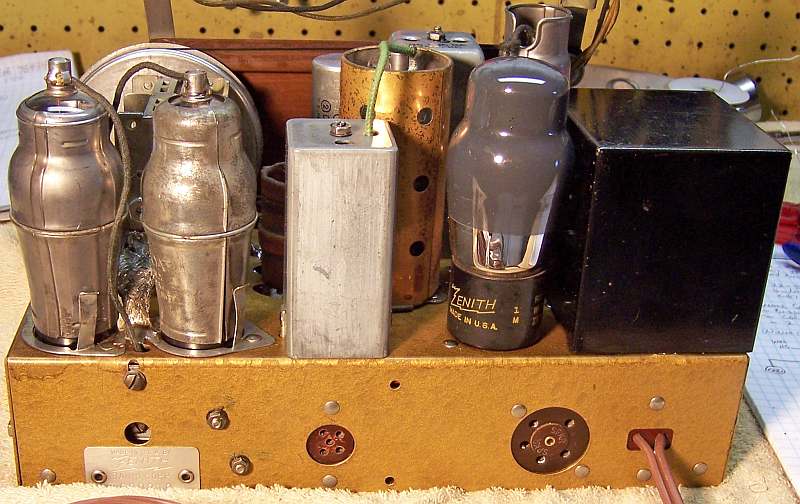
Chassis Before Restoration |
Chassis After Restoration |
 |
 |