Zenith 6S541BT (6-S-541BT) Restoration
 |
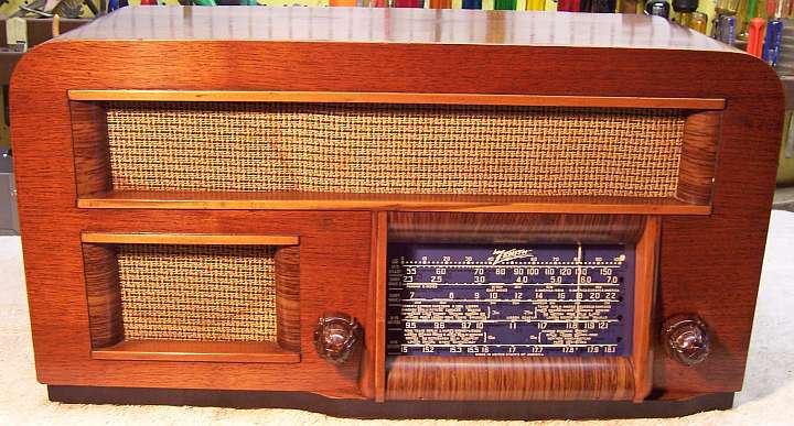
The Zenith 6S541BT from 1941 is a 6-tube AC Superhet
circuit radio that
receives the broadcast band and four short wave bands. The radio had been serviced in the past but most
of the original
parts were still in place. I
decided to try and reverse all prior servicing and restore the original chassis appearance if
possible. The model number has not been confirmed!
The schematic and a parts list for a near identical chassis 6B16BT can be found on-line on Nostalgia
Air. Any part number references in the text below reference that
schematic. |
My
antique radio restoration logs
Overview
The radio was purchased on eBay and was sold as working, at
least on the broadcast band. This was confirmed using a fused variac and watt
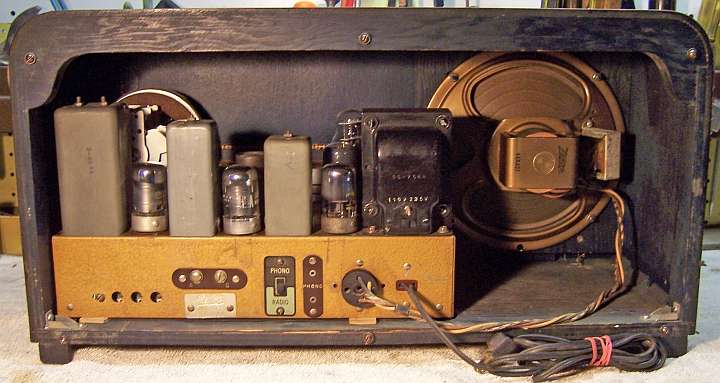
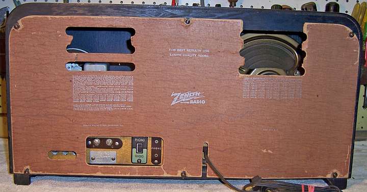
meter to slowly power up the radio. The radio appeared complete and in good condition. Even the back
cover was present. However there was damage to the back and several missing ventilation
slots. The model number and chassis number are unknown - there were no markings found anywhere - only a serial number S-969682
on a paper label inside rear chassis and on a metal plate on the outside back of
the chassis. Looking up the serial number on http://www.oldradios.com
Zenith Serial Number Search states that serial number S-969682 corresponds to chassis 6A11BT,
a radio designed for the export market. But chassis 6A11BT was not found at Radio
Museum or any other on-line source. I did find a chassis 6B16BT at Radio Museum for models 6S624BT and 6S643BT (as well as the AT and CT
versions of this chassis - different power options). My radio matches the photo
of model 6S643BT found at Radio Museum, listed as
circa 1948 (with a question mark). The schematic source for model 6S643BT
at Radio Museum
was Riders volume 19 (circa
1948 or sooner ), page Zenith 19-4, which matches my radio.
An inquiry on Antique Radio Forums about chassis 6A11BT resulted
in a response from Martin Blankinship, a well-known Zenith collector, expert and
author. The information he provided was from the Zenith Export Service Manual 1937-1942
which is neither available online nor for sale Martin provided a list of
possible model numbers that used chassis 6A11BT, along with the speaker size and
part number for each! His opinion was that my radio was likely model 6S541BT.
Chassis 6A11BT should be a 6 tube export chassis, circa 1941, with a dual
voltage power transformer.
The speaker in my radio is an 8" (used in 6S541BT) rather than the 6.5" (used in model
6S524BT table top).
Two of the tubes in my radio are branded Zenith (likely original) with date code 0Y
and Y0, which is likely circa
1940 (tube manufacturing date).
My chassis wiring and part numbers for components such as the IF transformers, speaker and filter capacitor
matches the Riders schematic for chassis 6B16BT and model 6S642BT with a few exceptions:
So for now I am going to assume that my radio is a Zenith model 6S541BT, chassis
6A11BT. That radio is a 6-tube superhet with an RF amplifier and untuned first detector stage (2 gang
tuning capacitor). It was obviously made in USA for the export market. The power transformer allows operation from 115 or 235 volts, 50-60
cycles. The set has phono
input, typical for export models. It is a five band radio with broadcast (medium wave) band, two
general coverage short wave bands, and two short wave band spread
bands (16-19m and 25-31m). It would have likely been used in Europe.
Previous Servicing
I always attempt to avoid purchasing radios that have been
"restored" by collectors or flippers, and am looking for either all
original examples or those which have been "lightly serviced" in the
distant past by radio service shops, rather than peppered with new film
capacitors. This radio had received some prior
servicing, but had not been badly hacked or restored. Most of the original
parts were still in place.
- Tubes 7J7, 7A7, 7C6, and 6X5GT/G likely had been replaced - none of these were branded
Zenith. The three Loctal tubes were branded Philco - likely NOT original in a Zenith!. Tubes 1232 and 6K6GT were
branded Zenith and were likely original (the 6K6GT date code was 0Y, the 1232
date code was Y0 -
1940?)
- Filter capacitor C16 (part 22-719 clamp mounted under the chassis) had been
removed (part of the clamp and attaching rivet remained) and an axial tubular capacitor 22mfd/450 volts tacked in.
- Filter capacitor C17 (a twist lock type with cardboard cover) had been
disconnected but left in place. A 22mfd/450 volt axial tubular had
been tacked in under the chassis to replace it.
- C15, a 0.004mfd/1000 volt line bypass had been replaced with a 0.01mfd/400
volt film capacitor (voltage rating marginal for even 115 volts, let alone
240 volts)!
- The AC line cord was black and likely had been replaced (the original was more likely brown, as shown in the photo in
Radio Museum). The cord had an integral molded USA type plug.
- All remaining wax-paper capacitors and all resistors were original.
Cleaning
The chassis was dusty, but not rusty. All tubes were removed. The dust was vacuumed
and blown off, top and bottom. After removal of
filter capacitor C17 (for restuffing) and first IF transformer (for replacement of
crumbling wiring) the top of the
chassis was cleaned using using old tooth brushes and a vacuum to removed dust
from the crevices.
Survey
In Zenith schematics, all
resistors and capacitors having the same value have the same part number call
out. So for example, there may be multiple R2's or C4's on the schematic.
Before I start work on the chassis I annotate the schematic so that all parts
have unique identifiers. I usually add an alphabetic suffix, so that the
part numbers are thus R1A, R1B, etc. I then annotate the schematic and under-chassis photo with
these unique part numbers using a red felt-tip pen. I then removed all
non-original capacitors, documenting their locations
and connections.
-
The radio actually worked on all bands even though all
wax-paper capacitors were original. So obviously there were no serious
problem. Even hum was minimal (the filter capacitors had been replaced
by recent types vs. older vintage types).
-
The dial lamps were OK.
-
The line cord was OK but likely not original. .
-
The tuning capacitor mounting grommets were OK, which is
fortunate, since the screws retaining them are underneath the complex and
fragile band
switch wiring.
-
The radio used mostly rubber covered wiring, all of which was bad.
If a wire were moved even a small amount, the insulation would break and fall
off, exposing the conductor.
Most of the wiring would have to be replaced. Great efforts were made
not to disturb the wiring around the band switch, since some attachment
points retaining this wiring were not accessible.
-
Only one resistor (R6, 1000 ohms) was out of
tolerance.
-
The 7A7 IF amplifier tube was weak.
-
The 6X5G tube had been replaced by a 6X5GT/G (one side of
which tested weak).
-
The 1232 (7G7) tested slightly weak in one tube tester but
tested OK for emission in another.
-
The 7B6 tube had been replaced by a 7C6 (an acceptable
replacement in parallel filament supply cases).
-
There was excessive friction between the volume and tone
control shafts such that when one was adjusted, the other would also move.
-
The band switch knob was slightly
warped likely due to excessive tightening of the set screw. The
associated shaft is a small diameter with a very shallow flat. If the
set screw is not correctly tightened, the knob will slip. The same is true of
the volume control shaft.
Restoration Strategy
Since the radio actually worked and was in good condition, I
debated about restoring it at all! Replacing all the rubber covered wiring
is difficult and prone to error. But I feared that if the capacitors and
wiring were not replaced, future capacitor failures or shorts could easily
destroy the radio. I have found that the majority of eBay radio sellers
will plug in the radio "to test it" if physically possible.
Experienced radio sellers often cut off the power cord if the radio is being
sold as needing restoration, untested, or for parts, since it may pass through
many hands over many years before someone attempts to test or restore it.
I assume that all paper and electrolytic capacitors are leaky and thus should be
replaced (I always "restuff" the original components if possible). I
do not replace mica capacitors, but may test them in place if possible (usually
this requires disconnecting one lead of the capacitor).
Since almost all of the original parts were still in place I decided to try
to maintain the
original chassis appearance to the extent possible. Normally I would
rebuild all original wax-paper capacitors as well as the filter capacitors in
their original cases (restuff them). Filter C17 was still intact and could be
restuffed. But C16 had been removed, so a reproduction replacement would have to be
fabricated. The out of tolerance resistor R6 (a 1000 ohm, 20% carbon composition
type) would be replaced with the same type I had in stock (which measured only
15.6% high).
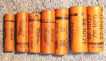
Unfortunately most of the paper/wax capacitors were branded Zenith but
likely made by Solar (Seald-Tite - part number
suffix "AM"). These are a solid
body of wax with a thin paper wrapper and cannot be restuffed! So I
decided to replace all of these capacitors with the more usual Zenith parts made with cardboard tubes
sealed on each end with wax, which can be restuffed and then resealed. I collect branded (Zenith, Philco, Sprague,
RCA/GE etc.) dud capacitors just for this case, and for cases where an original
part has been replaced by a modern part. The part number suffix (not shown in
the schematic) varies with the supplier. For example, a Solar branded part may
be coded 22-819 AM, vs. a Sprague or Cornell-Dubilier supplied part with the same value may be coded
22-819E or some other suffix letter.
In cases where I did not have the correct
Zenith part number which corresponded to the Solar provided part, I used a
Zenith part with the same capacitance and voltage rating. In a few cases,
I did not have a corresponding Zenith part in stock and had to use a Zenith part
with a
different voltage rating. For example: for C15, 22-806 AM, 0.004mfd/1000 volts (2 used in the
radio) I used Zenith
part 22-805E (.004/600 volt) restuffed with a 0.0047uf/630 volt capacitor. This
was marginally rated for the output tube plate capacitor, but I had no
other choice for restuffing and had no new 1000 or 1200 volt parts in stock
small enough for restuffing. I plan on researching a suitable 1000 or 1200 volt rated film capacitor that will
fit inside the original shell. If found, I will redo the restuff of
the capacitor that shunts the output transformer to the cathode of the 6K6
output tube. If this capacitor fails, it can take out the output
transformer!
When I replace a component, I
always remove the original part completely from a terminal. Other good components connected at the terminal are protected from heat using old medical
clamps (hemostats). Excess solder is then removed using a solder sucker in order to
expose terminal holes for reattachment of the rebuilt or replaced component.
Repairs
Rubber Covered Wiring
Most of the crumbling rubber covered wiring had to be
replaced. The insulation would fall off if the wire was even slightly
moved. Most of the existing wiring was about #24 solid in various
colors. To replace it, I used #20 cloth covered hookup wire (unrated
voltage),
available from Radio Daze
and possibly other suppliers. Their 600 volt rated wire is not suitable for
radio restoration - it is MUCH too large. One particular Zenith color, a grayish-green,
is not available. In this case I used green. One difficulty in using this wire
is that the conductor diameter is much larger than the original wire used. This
makes it difficult, or in some cases impossible, to thread multiple leads
through some component lug holes - and especially loctal tube socket lugs (which
I hate). While most wiring was replaced, I did NOT attempt to replace some
of the wiring around the band switch. Some of this wiring is not
accessible! The radio was apparently built in layers - some wiring and
components were attached before the band switch was installed. I took great care
to not disturb this wiring. I did manage to replace all filament and B+ leads,
as well as most signal level leads. In some cases with both wiring and
paper/wax capacitor replacement I was forced to change the ground attachment
point, since the original ground connection was not accessible (buried under the
band switch). The two trimmer capacitor groups near the band switch had to
be gently moved out of the way in order to access the wiring beneath them.
In one case, a lead to the band switch was disconnected at the trimmer in order
to prevent possible damage when moving the trimmer.
Wax/Paper Capacitors
Two original paper/wax capacitors were cardboard tube types and could be
restuffed. These two and all of the replacement Zenith
cardboard tube paper capacitors were rebuilt in their original cases
using modern 630 volt film capacitors in order to maintain the original
under-chassis appearance. For C13, 22-1117 500pf @ 600 volts, I used two
0.001mf/630
volt film capacitors in series. They just fit inside the original case end
to end.
My re-stuffing process is as follows:
- The original capacitor is removed from the radio, and the required lead
length and any insulating sleeving use noted.
- The low melting point wax from each end of the original or replacement
capacitor is melted and removed using an old
25 watt soldering iron.
- The original wire leads are removed, as well as any remaining wax.
- While the internal wax is still molten, a small screwdriver is used to push out the
original paper-foil roll. In some cases, the contents comes out when the leads
are pulled out.
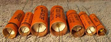
- The original cases are then cleaned out, and any wax and dirt on the
outside removed by gently heating the body over a small alcohol lamp and
wiping with a paper towel while still molten. At this point, the cases
look like this (these examples are from a different Zenith radio I
restored):
- If the required lead length is longer than that of the replacement
capacitor, a piece of buss wire is attached before restuffing. The splice is
hidden inside the tube.
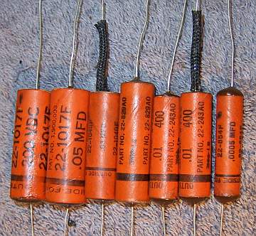
- The replacement capacitor is wrapped in a narrow strip of
paper towel in order to keep the new capacitor centered and to keep it from falling out. Here
are the finished capacitors before sealing the ends.
- The finished capacitor is then sealed with melted rosin (salvaged from
early RCA Superhet catacombs, and donated by or purchased from members on Antique
Radio Forums). I do NOT recoat the outside of the rebuilt
capacitors with wax (I'm not sure what was originally used - probably
beeswax).
Filter Capacitors
The original clamp mounted tubular filter capacitor C16 (part
number 22-719, 16mfd/350 volts) had been removed and replaced by an axial
tubular capacitor. Remnants of the original clamp and rivet remained, and
provided a reference for where the original was attached. C17, a twist-lock
chassis mounted capacitor with a cardboard cover, had been left in place and
disconnected. Rather than just tacking in new modern electrolytics, I
decided to attempt to reproduce the original C16 and to restuff C17. I had
photographed an original Zenith part number 22-719C for reference in a previous
restoration. I was able to use it as a model to
fabricate a reproduction label with similar fonts, colors, and labeling. A paper label was fabricated using
Microsoft Word. It
contained the correct Zenith part number, capacity and voltage. I found a
suitable dud
clamp mounted capacitor in my dud stock. The cardboard case was cleaned
out. Rather than attempting to remove the clamp without damaging the case,
the label was split in two parts and attached on both sides of the clamp.
It was attached using GC Service Cement.
The original power supply filter capacitor C17 was removed and restuffed.
It was a 20mfd @ 450 volt FP twist lock type capacitor. It was restuffed using
a 22mfd 450 volt axial capacitor. My
procedure for restuffing FP type can capacitors is as follows (there are many
discussions and examples with photos using slightly different techniques on Antique
Radio Forums):
- Remove the cardboard cover. In this case, I had to use a heat gun to
soften the tar
holding it to the can. The outside of the metal can was cleaned of excess tar using lacquer
thinner.
- Uncrimp the bottom using a small screwdriver and diagonal cutters (try to
minimize damage to the outside of the can)
- Remove the mounting ring, the terminal board and the gasket behind,
cutting the aluminum leads to the capacitor body to free up the terminal
board.
- Remove the can contents using a heat gun to release the tar, followed by a
thorough cleaning using mechanical means, followed by lacquer thinner.
- Connect the replacement capacitor leads to the original terminals by
drilling small holes through the terminal board close to the terminal,
passing the positive lead through, and soldering it to the terminal on the
outside. The common ground lead is extended using bare buss wire and passed through a small hole drilled near
one of the capacitor ground/mounting tabs. This lead is not soldered
to the ground lug until after the capacitor is secured in the chassis
mounting wafer (otherwise the solder would prevent the lug easily passing
through the hole in the mounting wafer or could damage the wafer - ASK ME
HOW I KNOW THAT). The added ground lead extension is normally not needed if
radial capacitors are used.
- Reinstall the terminal board and mounting ring and restore the crimp
around the base (I use a plastic faced hammer).
- Reinstall the cardboard cover (it was not glued - just held by friction).
The cover hides any signs of the bottom crimp being disturbed.
An Original C16
|
The Restuffed C17
and Reproduced C16
|
 |
 |
Tubes
The bad 6X5GT/G was replaced by a Zenith branded 6X5G, which originally would
have been used. The weak 7A7 was replaced (Philco branded). The installed
7C6 tube was replaced by the correct 7B6 (Philco branded). All other tubes were
left in place.
Other Repairs
The line cord (black, likely a replacement) was left in place. I
originally wanted to use a brown vinyl cord, but found that most available
replacements are too large to pass through the chassis entrance insulator board.
I was NOT able to free up the volume and tone control shafts. I tried some
oil, but that did not help. Very likely the outer shaft had been deformed
somewhat due to excess tightening of the tuning knob set screw. The only possible
fix would be to replace the combination volume and tone control - impossible!
The warped volume and band switch knobs were left in place.
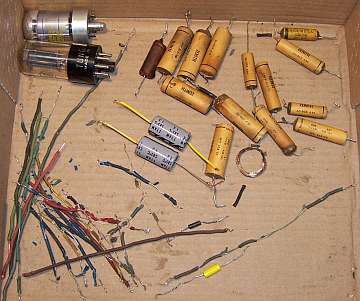
Bad Parts & Wiring
|
 |
Testing and Alignment
Once the radio had been reassembled,
the radio was powered up slowly using a fused Variac. This allows the
filter capacitors to reform. A DVM monitored the B+ voltage. The radio came alive and
actually worked on all bands. The set was then aligned. I did not bother
to align the short wave bands, as they worked very well and my signal generator
does not work well above 9mHz, and is not very accurate. I have to use a
frequency counter to confirm any frequency used. The IF transformers were way
out of adjustment. The broadcast band dial calibration was off about
50kHz. The broadcast band padder was very close to correct.
The radio worked well and sounded great with its large 8"
electrodynamic speaker, large cabinet, and loudness compensation type tone
control. The set seemed to perform
best with a 6' length of wire for an antenna! It did not seem happy using my 40'
indoor antenna strung across my basement ceiling.
Cabinet
The cabinet was vacuumed then cleaned using GoJo (white) hand cleaner and 00
steel wool.
Restoration Results
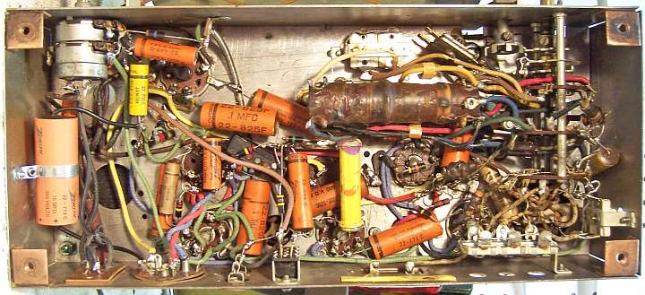
Chassis Before Restoration
|
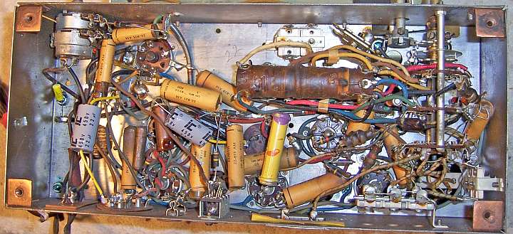 |
Chassis After Restoration
|
 |