Zenith 7S433 (7-S-433) Zephyr Restoration
 |
The Zenith model 7S433 (7-S-433) "Zephyr" from 1940 is a small tabletop
7-tube AC superhet circuit radio with a unique cabinet design based on the
railroad train with the same name.
It receives the standard broadcast band and two short wave bands, has
"automatic" or push-button tuning, and the Zenith Radiorgan
tone control (but has only two controls rather than the usual 5 or 6) The radio had seen
extensive servicing
and "electrical restoration" in the past - likely by a collector
- and very sloppily. I
decided to try and restore the original top and bottom chassis appearance if
possible and to reverse previous repairs and restorations to the extent
possible.
The schematic for the Zenith 7S433 Chassis 5721 can be found on Nostalgia
Air. Any part numbers mentioned will refer to numbers on that schematic. |
My
antique radio restoration logs
Overview
There are two different chassis used in model 7S433: chassis 5721
and 5724. My example used chassis 5721. Chassis 5721 uses a voltage
doubler rectifier circuit with two 25Z6G dual-diode tubes and a 25AC5 direct
drive triode audio power amplifier. Chassis 5724 uses a power transformer with a
single 6X5G rectifier. In order to maintain 7 tubes, and thus the 7S433
model number, Zenith replaced the 6Q7G triode-duodiode with a 6J5G detector
(diode) and 6F5G audio amplifier and added an RF amplifier stage. I would guess
that the 5724 chassis would have much better performance, although there are
still only two tuned circuits used (the converter input is untuned on the 5724
chassis).
The radio worked when received, although the seller stated that
it should be serviced before use. This is a very difficult radio to
service. The chassis is very compact, and the automatic tuning unit is
under the chassis. Some parts cannot be accessed without partial
disassembly.
Previous Repairs
-
The radio had been partially recapped, likely by a radio collector. However, capacitors that would have been difficult to
replace due to their location were NOT replaced.
-
The voltage doubler input capacitor C19 had been replaced,
but the main filter capacitor C20/21/22 was original.
-
A new AC line cord and plug had been installed
-
All the tubes were replacements, except for the Zenith 6AF5G,
which was good.
-
The shield base for the 6K7G IF amplifier tube had been
wrecked. Originally the shield base would have only accepted G type
tubes, and metal or GT types could not have been used. So likely
sometime in the past a metal or GT type tube would have been used with the
existing shield (since Zenith usually did not ground pin 1 of the tube -
again to prevent use of metal or GT type tubes). A 6K7G tube was
installed when I received the radio.
-
The volume control circuit had been modified. The
capacitor C12 which should feed the hot end of the volume control was
instead connected to the CENTER wiper terminal, along with the capacitor
feeding the first audio amplifier. A 1 meg dogbone type resistor was
connected from the tone control tap on the volume control to the hot end -
nothing else was connected at that lug. I also noticed that the lug for the hot end of the volume control was
mostly missing (broken). I am really not sure why this modification was
done. Since a dogbone type resistor was used, I suspect this was not a
recent modification. The volume control was good (but needed
cleaning).
-
All original chassis bolts and rear cover finishing washers
and screws were either missing or replaced with generic hardware.
Survey
My usual restoration procedure is to first make a complete
survey of the condition of all components. The survey results guide my
restoration strategy. If major and unique components are defective or
missing and
cannot be restored or replaced, I may elect to sell the radio rather than restore it.
I always assume that all paper and electrolytic capacitors are leaky and thus should be
replaced (I always "restuff" the original containers if possible).
Any mica capacitors are assumed OK until testing proves otherwise. The
automatic tuning unit (push button assembly) was removed in order to gain access
to the other components. Fortunately, only two wires had to be
disconnected. I found:
-
Since the radio actually worked, no extensive survey was needed.
-
The AC power switch was bad (measured high resistance) - dirty and/or oxidized contacts likely.
-
Two dogbone resistors were out of tolerance. The remaining resistors were
within tolerance.
-
Six original Zenith paper/wax capacitors were still in place, but 10 had
been replaced with mostly radial film capacitors of various types.
-
C19, the voltage doubler input capacitor, had been replaced. However,
the replacement capacitor did not have a protective cardboard cover, and it
is connected directly to the AC line! Since the radio has a
protective back cover, this would normally not be a serious issue.
However the back must be removed in order to switch from radio to TV audio
input mode and connect the audio cable to the chassis jacks (this function
was likely just a marketing gimmick). The original main filter
capacitor C20/C21/C22 was still in place.
-
Wiring from the Wavemagnet loop antenna to its chassis connection plugs was
frayed and insulated using adhesive tape in order to prevent shorts.
All the remainder of the wiring was in good shape - there was no crumbling
rubber covered wiring in this radio.
-
The two 25Z6 tubes, the 25AC5, and the 6A8 tubes were GT types. The 6K7G and 6AF5G
were good (6AF5G was an original Zenith). The 6Q7G was very weak.
-
The tip of one of the Radiorgan tone control switches was broken off.
-
The chassis washers and tuning capacitor mounting grommets were bad, which is typical.
Repairs
All tubes and shields were removed. The automatic tuning unit was
removed. The dial scale and pointer were removed (the remaining dial cord
was taped to the pulley for ease of reassembly - the dial cord would be VERY
difficult to replace in this radio - access to the dial drive is blocked by a
coil). All non-original parts and both
filter capacitors were then removed. Since 10 original Zenith capacitors
had already been replaced, I did not pay much attention to the placement of
those replacement capacitors, except to where they were connected. The volume control was
removed for cleaning and to check out the broken lug. The oscillator trimmer capacitors and oscillator coil were moved
out of the way for access. They do not have to be disconnected, but the
ground buss to the trimmers and a couple of leads from the band switch to the
Wavemagnet socket on the rear chassis have to be disconnected. I then took photos of the chassis
bottom so that routing of wiring and component placement can be restored.
Lead dress is often critical in radios. When I replace a component, I
always remove the original part completely from a terminal. Other
components connected at the terminal are protected from heat using old medical
clamps. Excess solder is then removed using a solder sucker in order to
expose terminal holes for reattachment of the rebuilt or replaced component.
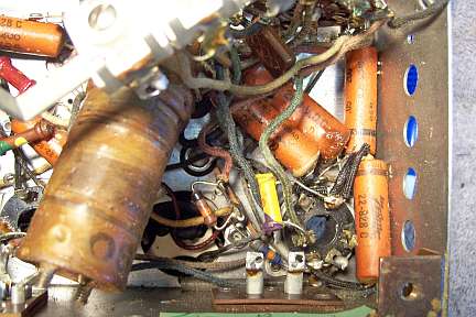
At this point, the chassis appeared as follows:
The volume control switch was flooded with Big Bath cleaner and cycled many
times. The switch eventually worked. The automatic tuning contact springs were cleaned with lacquer thinner
on a pipe cleaner followed by DeOxit and then more
lacquer thinner and a pipe cleaner.
The broken Radiorgan tone switch pull was replaced using one from a donor
switch assembly in my parts bin. The original phenolic link was first
fully depressed and then cut
about 3/32" from the switch frame using a hobby razor saw. The phenolic link on the
replacement was then cut at the same point, but leaving it a little long! The two parts
were then filed smooth and measured to make sure the switch pull projected the
correct distance from the switch body when pressed in. The two parts were
first joined using super glue, and then epoxy.
The top of the chassis was cleaned with GoJo hand cleaner and 00 steel
wool.
Resistors and Capacitors
All original Zenith paper capacitors remaining were rebuilt in their original cases
using modern 630 volt axial film capacitors in order to maintain the original
under-chassis appearance. I reseal the cardboard tubes using rosin
salvaged from RCA catacombs (it melts at a low temperature and will not damage
the replacement capacitors). I collect original Zenith (as well as Philco
and other branded types) wax/paper capacitors for use when the originals are
missing. Zenith schematics in Riders Manuals indicate the Zenith part
numbers of the capacitors used. I was able to find the correct part
numbers for most of the missing original Zenith capacitors in my stocks.
In some cases I did not have the correct part number dud in stock, but did have a Zenith part
with the same value and voltage rating. In a couple of cases, I was forced
to use a part with a different voltage rating. For example, the original
might have been a .01mfd at 600 volts, which was replaced by a .01mfd at 400
volts. In all cases, these
capacitors were restuffed with modern 630 volt film capacitors and resealed.
One original Zenith filter capacitor C19 had
been replaced - and the replacement did not have a cardboard cover. I found a dud FP type electrolytic capacitor in my junk
capacitor box which had the correct diameter and length and had a cardboard
cover. This capacitor was opened, its contents removed, and was rebuilt using
a modern 33mfd/160 volt electrolytic cap. The dud FP capacitor I used had 2 lugs. One was removed. I did
NOT attempt to modify the label on the cardboard cover. The original main
filter capacitor C20/C21/C22 was 30/20/10mfd at
350/250/250 volts. It was rebuilt as 33/22/10mfd at 350/250/250 volts
using new modern radial lead electrolytics.
The two dogbone resistors that were out of tolerance were replaced by a NOS dogbone
resistor (that was in tolerance) and another that had drifted to near the correct value.
That one was repainted
using hobby paint to the correct color codes. While this resistor may
continue to drift, so will the others in the set. I wished to maintain the
original above and below chassis appearance.
Tubes
Correct G type tubes were installed. I had a new Zenith 25AC5 in stock,
still in its original Zenith container. I also had one Zenith 25Z6G in
stock. A second 25Z6G was found on eBay. I had a good 6Q7G and 6A8G
in stock. I attempted to straighten the damaged 6K7G shield base as good as possible. In any case it is hidden by the tube shield.
Testing and Alignment
Once the radio was reassembled and the tubes installed, power was brought up
slowly using a variac. AC power consumption was monitored using a watt meter, and a
DVM monitored the B+. The radio came alive immediately and worked.
The set was then aligned - no surprises. The radio is difficult to
align because the loop antenna and speaker must be connected while it is
aligned. One trimmer is under the chassis! The IF transformers were
way off - set to about 470Kc. The broadcast band peaked up nicely. The push buttons were
adjusted to local stations.
The radio performs well, and has very good tone on the broadcast band. The short wave performance
was disappointing. However, this is really just
a 5 tube radio with no RF amplifier stage.
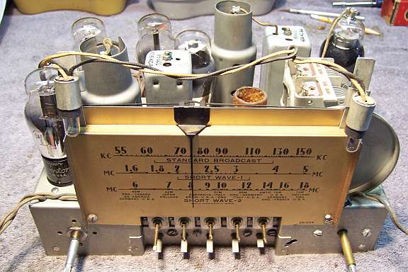
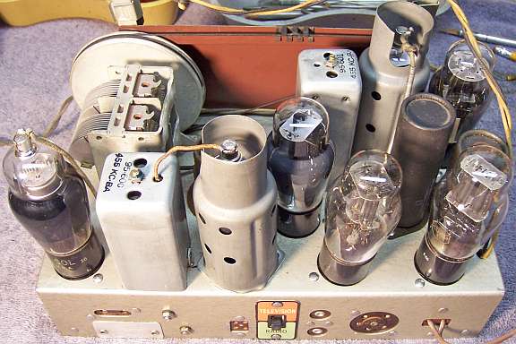
Restoration Results
In the BEFORE chassis photo, the push-button tuning unit and tuning capacitor
have been removed for access.
|
Chassis Before Restoration |
Chassis After Restoration |
 |
 |