This example had seen minimal servicing in the past. I decided to reverse previous repairs to the extent possible.
The schematic for the Zenith 7-S-529 can be found on Nostalgia Air. Any part numbers will refer to numbers on that schematic.
|
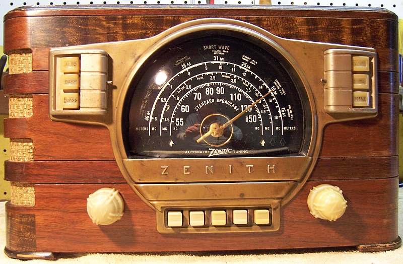
The Zenith model 7S529 (7-S-529, (1941 model year) is a tabletop
7-tube AC superhet circuit radio.
It receives the standard broadcast band and two short wave bands, and has
"automatic" or push-button tuning and the Zenith RadiOrgan tone
control system. This example had seen minimal servicing in the past. I decided to reverse previous repairs to the extent possible. The schematic for the Zenith 7-S-529 can be found on Nostalgia Air. Any part numbers will refer to numbers on that schematic. |
My antique radio restoration logs
The 1232, 7A7, 7B8, 7A4, and 7B4 were branded Zenith and likely originals.
The 6F6G had been replaced with a 6K6GT
The 6X5G had been replaced with a 6X5GT
C8, part number 22-327 (.02/200) had been replaced (volume control center)
The power cord had been replaced and the power line antenna removed.
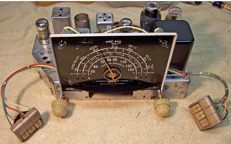
The leads to both tone control panels had been cut, likely by the seller in order to pull the chassis (the two tone control panels will not pass through the escutcheon holes - the switch assembly has to be removed first).
The radio was very dirty and there was considerable rust on the power transformer and some on the chassis.


My usual restoration procedure is to first make a complete survey of the condition of all components. The survey results guide my restoration strategy. If major and unique components are defective or missing and cannot be restored or replaced, I may elect to sell the radio rather than restore it. I always assume that all paper and electrolytic capacitors are leaky and thus should be replaced (I always "restuff" the original containers if possible). Any mica capacitors are assumed OK until testing proves otherwise.
The automatic tuning unit (push button assembly) was first disconnected in order to prevent damage to the fragile coils during handling the chassis. Fortunately, only three wires had to be disconnected. The wave trap assembly was removed for access. I found:
I first removed all the non-original components, documenting their locations and connections. All tubes and shields were removed. The tuning capacitor was then removed for cleaning access to the chassis, and to replace the mounting grommets (I used standard rubber grommets). The power transformer was removed in order to remove the rust and repaint the case. I then took photos of the chassis bottom so that routing of wiring and component placement could be restored. Lead dress is often critical in radios. When I replace a component, I always remove the original part completely from a terminal. Other components connected at the terminal are protected from heat using old medical clamps. Excess solder is then removed using a solder sucker in order to expose terminal holes for reattachment of the rebuilt or replaced component.
The top of the chassis was cleaned with GoJo hand cleaner and 00 steel wool. The tuning capacitor was cleaned in an old Heathkit ultrasonic cleaner with dilute ammonia. After drying, the bearings were lubed with automotive distributor cam grease. The power transformer was removed, power wire brushed, and repainted using semi-gloss spray enamel.
All the original Zenith paper capacitors were rebuilt in their original cases using modern 630 volt film capacitors in order to maintain the original under-chassis appearance. I reseal the cardboard tubes using rosin salvaged from RCA catacombs (it melts at a low temperature and will not damage the replacement capacitors. One original capacitor had been replaced: C8, part 22-387 (.02mfd 200 volts). Fortunately I had an original capacitor in my stocks, and it was restuffed in order to reverse the previous repair.
Both original filter capacitors were still in place. C20, part number 22-1036C (14mfd/450 volts) was cleaned out and restuffed with a 15mfd/450 volt capacitor. C18/C19, a chassis mount FP type capacitor, was restuffed. The original was 5mfd/450 volts plus 15mfd/350 volts. It was restuffed using new 4.7mfd and 15mfd, 450 volt capacitors. The original can was restuffed using the following technique:
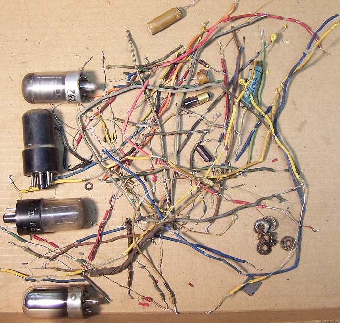
Most of the original rubber covered wiring had to be replaced. The insulation would crumble and fall off if the wiring was moved even the slightest amount. A few wires between the bandswitch and coils were left in place, since they did not have to be disturbed. The cables to the tone control panels had to be replaced (they had been cut), as well as the wiring to the first IF transformer. Here is the collection of defective parts and wiring!
A new 6X5G tube was installed to replace the existing 6X5GT. A 6F6G tube was installed to replace the 6K6GT. I found a good 7G7 tube (1232) and NOS 7B4 tube in my stock. The remainder of the tubes were good.
Once the radio was reassembled and the tubes installed, power was brought up slowly using a variac. AC power consumption was monitored using a watt meter, and a DVM monitored the B+. The radio came alive immediately and worked. Once working, the push button tuning assembly was reinstalled.
The set was then aligned - no surprises. The push buttons were adjusted to local stations without difficulty. The set worked well on all bands, and the RadiOrgan tone control operated correctly.
|
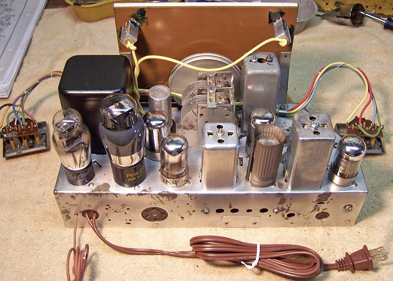
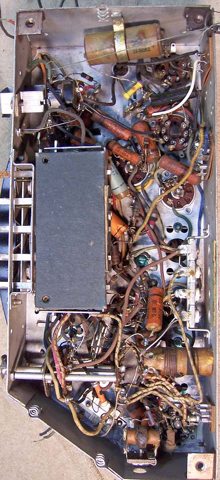
Chassis Before Restoration |
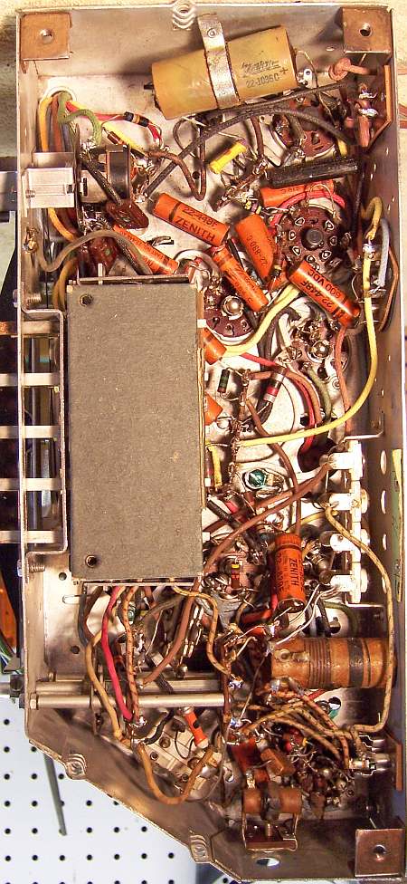
Chassis After Restoration |
 |
 |