Zenith 805 Cathedral Restoration
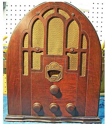 |
The Zenith model 805 Cathedral from 1935 is a small tabletop
5-tube AC superhet circuit radio. According to the Western
Historic Radio Museum, the Zenith 805 was the last cathedral style
cabinet made by Zenith. The radio receives the broadcast band and
one short wave band. The radio had seen
extensive servicing
and "electrical restoration" in the past - likely by a collector
- and was very sloppy work. As received, the radio did power up, but there was no reception. I
decided to try and restore the original top and bottom chassis appearance if
possible and to reverse previous repairs and restorations to the extent
possible. This turned out to be a real challenge!
The schematic for the Zenith 805 can be found on Nostalgia
Air. Any parts numbers mentioned will refer to numbers on that schematic. |
My
antique radio restoration logs
Previous Repairs
-
The grille cloth had been replaced.
-
The radio had been partially recapped, likely by a radio
collector rather than a service technician. Seven original Zenith
capacitors had been replaced. Capacitors that would have been difficult to
replace due to their location were NOT replaced. Many capacitors
were the wrong values and types, and some were not even soldered in (leads
just wrapped around a terminal or other component). For example, the
tone control capacitor (.03mfd) had been replaced by a .5mfd unit!
This high value would have surely killed most of the audio. The
oscillator feedback capacitor (.01mfd MICA) had been replaced by a paper
capacitor. New filter capacitors had been tacked in.
Fortunately, the original can type filters were still in place.
-
All the tubes were replacements.
-
Two goat type tube shields were missing.
-
Two power resistors were tacked in to repair two open
sections of the Candohm metal clad power resistor .
Survey
My usual restoration procedure is to first make a complete
survey of the condition of all components. The survey results guide my
restoration strategy. If major and unique components are defective or
missing and
cannot be restored or replaced, I may elect to sell the radio rather than restore it.
I always assume that all paper and electrolytic capacitors are leaky and thus should be
replaced (I always "restuff" the original containers if possible).
Any mica capacitors are assumed OK until testing proves otherwise. I found:
-
All 11 original dogbone resistors were out of tolerance (by more than 20%).
Two sections of the Candohm wire wound resistor were open (5700 ohms and 11K
ohms). The bias portions (250 ohms and 85 ohms) were OK.
-
Only three original Zenith paper/wax capacitors were still in place, and
seven had
been replaced with capacitors of various types and sizes.
-
All tubes checked OK.
-
The output transformer primary was open (likely the reason the radio did not
work as received!) This may have been caused by the
"restorer" or repair tech installing a 0.5mfd capacitor as the
tone control capacitor (should have been 0.03mfd) which is from the output
tube plate to ground. Another possibility is that the original
capacitor shorted and took out the output transformer.
-
The power transformer, speaker field coil and all IF and RF transformers
were OK.
-
The IF amplifier cathode resistor looked original, and was 990 ohms (it had
drifted to 1125 ohms). The schematic and other information I had, as
well as other radios used for reference, indicated that the value should be
300 ohms. A 300 ohm resistor was installed. The 990 ohm value
may have been an official Zenith change.
-
The chassis washers were bad, which is typical.
-
The power cord had a break near the chassis entry grommet and one other place, but
was original. The plug was old style, but likely a replacement.
-
The power switch on the volume control was bad - likely corrosion or
dirt. The volume control itself appeared OK.
-
Some wiring, including the cable to the speaker, was in bad condition and
would have to be replaced.
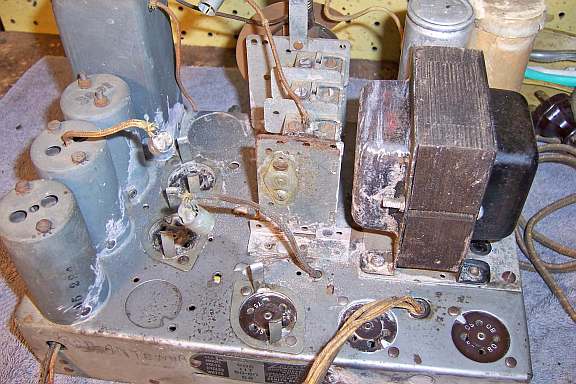
Cleaning
One of the first things I noticed was that there was some sort of CRUD on the
top of the chassis and on some of the chassis top components (in the photo
below, the right side of the power transformer had already been cleaned).
This material was very hard and almost impossible to remove. I tried soap and water,
paint thinner, vinegar, ammonia and lacquer thinner. None of these would
remove it! Even a Dremel Moto Tool with a wire brush had difficulty.
I could remove it using GoJo hand cleaner and 00 steel wool, but with great
difficulty. There were lots of suggestions from the friendly folks on Antique
Radio Forums, but none of the suggestions helped. So I just continued
using the GoJo and 00 steel wool, manual scraping, and the Dremel. This
also removed the paint on the power transformer. I eventually removed all
chassis top components for cleaning (one at a time). The tuning capacitor
was cleaned in a dilute ammonia solution in an ultrasonic cleaner, followed by
soap and water and a tooth brush, then after drying, some wire brushing to
remove some of the rust. The power transformer case was wire brushed and
then repainted.
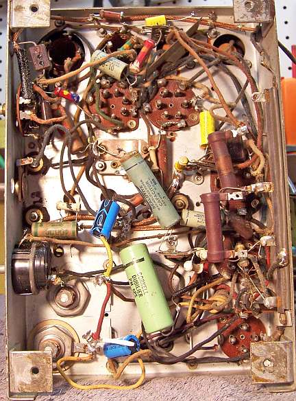
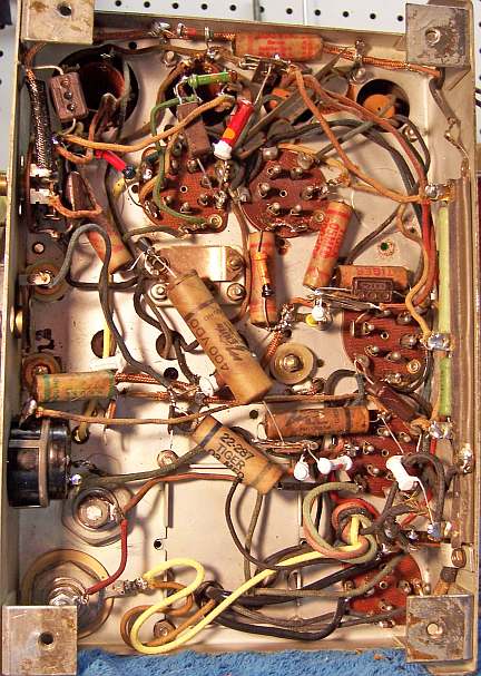
Repairs
Since the radio had been so badly hacked, an Antique
Radio Forums member was able to provide me with a mostly original 805 under chassis photo. This was used for component placement and routing of
wiring.
The volume control switch was flooded with Big Bath cleaner and cycled many
times. The switch eventually worked.
The open output transformer was replaced by a Stancor A-3850 8-watt universal
replacement transformer from my parts stock. This particular transformer
had one side of the primary OPEN. But this worked out OK since this radio
had a single-ended output stage. The speaker voice coil measured 3.1 ohms
DC resistance. I estimated the impedance as 3.4 ohms. The type 42
output tube needs a plate load of about 7000 ohms. So the required ratio
is 45:1. I was able to come close to this ratio using lugs 4-5 of the
secondary (47:1). The mounting centers of the replacement transformer was
the same as the original: 2".
I had the required TALL Goat tube shields in my stock. They had to be
cleaned up on a bench grinder with a wire brush to remove the rust.
All grid leads, as well as the speaker cable, had to be replaced. The
original power cord was cut at the chassis entry grommet and reinstalled. One bad
place in the cord was repaired using shrink tubing and electrical tape.
While somewhat unsightly, at least the original cord was saved.
For chassis washers, I used part CW-6 (1/8" thick) from Renovated
Radios. These placed the control shafts at the correct height.
For the tuning capacitor grommets, I used part GSm-Tuner with the smaller
diameter part sliced off using a razor blade (six needed).
Resistors and Capacitors
I have noticed that 1935-1936 (and possibly other) Zenith radios used
capacitors made by Sprague and Cornell Dubilier, but with Zenith part
numbers. Some were branded TIGER, but again, had Zenith part numbers
(22-xxx). Later on, all Zenith capacitors were orange in color and were
branded Zenith.
All original Zenith paper capacitors remaining in the radio were rebuilt in their original cases
using modern 630 volt axial film capacitors in order to maintain the original
under-chassis appearance. I reseal the cardboard tubes using rosin
salvaged from RCA catacombs (it melts at a low temperature and will not damage
the replacement capacitors). I collect original Zenith (as well as Philco
and other branded types) wax/paper capacitors for use when the originals are
missing. Zenith schematics in Riders Manuals indicate the Zenith part
numbers of the capacitors used. I was able to find the correct part
numbers for most of the missing original Zenith capacitors in my stocks.
In some cases I did not have the exact dud in stock, but did have a Zenith part
with the same value and voltage rating and a later part number. For
example, one original missing part n umber was 22-170 - I used a 22-170F which was the same
value but likely a later version. In all cases, these dud replacements were
restuffed with modern 630 volt film capacitors and then resealed.
A 0.01mfd 400 volt mica capacitor was installed for the oscillator feedback
capacitor (22-276). I did NOT have a Zenith part in stock this case - an Aerovox unit was
installed. Another 250pf mica capacitor was leaky (22-182, RF bypass
capacitor across the volume control). Again, an Aerovox was installed to
replace it.
The original filter capacitor cans (8mfd) were restuffed using new 10mfd/450 volt
capacitors. The cardboard sleeve was removed from the input filter
capacitor. The cans were then mounted in a Unimat lathe and deeply scored
about 3/4" up from the base. They were then cut in two using a hobby
razor saw. The contents were removed. The original center studs were
cut short, drilled, and a ground lug installed using 4-40 hardware. The + lead of the
replacement capacitor was attached to this lug. The negative lead of the
new filter was extended using bare buss wire to the base of the can where a
small hole was drilled. Insulating spaghetti tubing was used to prevent
shorts. The buss wire was later placed in contact with either the chassis
or the ground terminal of the filter capacitor. The two halves of the cans
were then rejoined using 3/4" PVC plumbing couplings and epoxy. This
makes for an almost invisible repair. The cardboard cover was reinstalled
on the input filter capacitor.
The eleven dogbone resistors that were out of tolerance were replaced by
either NOS dogbone
resistors that were close enough to the needed value, or with others that had
drifted to near the correct value. The resistors that had drifted were repainted using
enamel hobby paint
to the correct color codes. For example, one resistor needed was a 29K 1/2 watt
dogbone. It was replaced by a 20K 1/2 watt dogbone that had drifted to
31.46K, which is within tolerance. While these resistors may continue to drift, so will the others in the set. I wished to maintain the
original above and below chassis appearance. I collect all the NOS and
used dogbone resistors I can find, just for this purpose, and never throw one
away!
Less obtrusive power resistors were used to replace the open sections of the
Candohm metal clad power resistor. These were placed under the Candohm and
attached to the original terminals. The open sections were first checked
for leakage to ground and between terminals using a current limited 450 volt DC
source and a milliamp meter. The terminals are wiggled during the
test. If there is any hint of leakage or intermittent continuity, I would
instead install terminal strips and NOT use the original Candohm terminals.
Testing and Alignment
Once the radio was reassembled and the tubes installed, power was brought up
slowly using a variac. AC power consumption was monitored using a watt meter, and a
DVM monitored the B+. The radio came alive immediately and worked.
The set was then aligned. I noticed that if the IF transformers were
adjusted for best results, the set would break into oscillation. I had to
slightly detune a couple of adjustments to prevent this. This MAY have
been why the IF amplifier cathode resistor (300 ohms in the schematic) was found
to be 990 ohms originally. Perhaps this was a production change. I
left the 300 ohm resistor in place. The radio performs well, and has very good tone on the broadcast band.
The volume control was really not in good shape. It was the type that
did not respond well to cleaning (a metal ring compressed against the resistance
element - I have found that attempting to clean these types will destroy the
resistance element). It worked OK, but during rotation the set would break into
oscillation (likely due to loss of contact on the center element). I did
not replace it in an attempt to maintain originality. This set will likely
be a SHELF QUEEN rather than a daily driver.
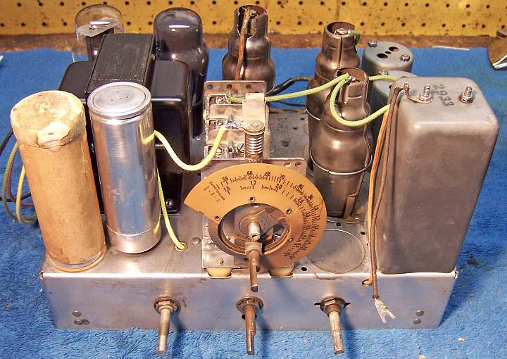
Restoration Results
|
Chassis Before Restoration |
Chassis After Restoration |
 |
 |