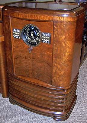
Zenith 9S367 (9-S-367) Restoration
 |
The Zenith model 9S367 (9-S-367) from 1939 was a my first (to
date) Zenith shutterdial set. It is a 9-tube AC superhet circuit
console.
It receives the standard broadcast band and two short wave bands, has
"automatic" or push-button tuning, and the Zenith Radiorgan
tone control The radio worked (at least it powered up and made
noise) when received. It was later discovered that the radio was
almost 100% original - almost no prior servicing had been done. I
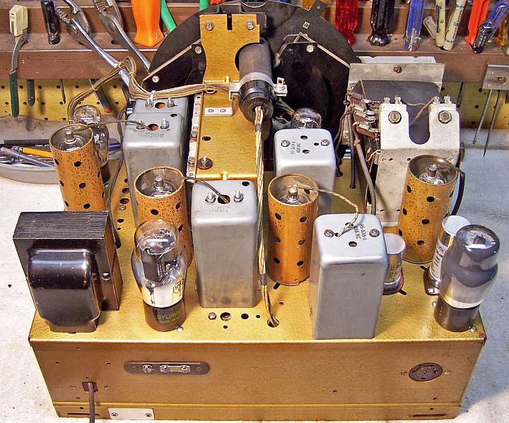
decided to try and maintain the original top and bottom chassis appearance and to reverse previous repairs to the extent
possible.
The schematic for the Zenith 9S367 can be found on Nostalgia
Air. Any part numbers mentioned will refer to numbers on that schematic. |
My
antique radio restoration logs
Previous Repairs
-
Only the 6U5 eye tube was branded Zenith. It was very
weak, and likely the original tube. All the other tubes had been
replaced.
-
R12 (220K) had been replaced.
-
R17 (10K) had been replaced (remnants of the burned original
remained).
-
C12 (oscillator circuit) had one lead cut - it had likely
shorted and burned R17.
Survey
My usual restoration procedure is to first make a complete
survey of the condition of all components. The survey results guide my
restoration strategy. If major and unique components are defective or
missing and
cannot be restored or replaced, I may elect to sell the radio rather than restore it.
I always assume that all paper and electrolytic capacitors are leaky and thus should be
replaced (I always "restuff" the original containers if possible).
Any mica capacitors are assumed OK until testing proves otherwise. Since the radio actually worked, no extensive survey was
needed, as major components were OK.
-
All station ID tabs were missing
-
Seven tone tabs were missing (only the OFF tab remained)
-
The tip of one of the Radiorgan tone control switches was broken off.
-
The radio had been fitted with 3 metal tubes (6F5 and two 6K7s), and 3 tube
shields were missing. The remainder of the tubes were good or slightly
weak. A 5Y4GT had been installed instead of a 5Y4G.
-
The 6U5 eye tube was very weak (likely the original Zenith)
-
The dial drive cord was stiff and did not work.
-
One shutterdial return spring was missing.
-
The AC power switch indicated high resistance - likely needed cleaning.
-
The power cord and plug were original and OK
-
Two 1 watt dogbone type resistors were not in tolerance.
-
Three carbon composition type resistors were not in tolerance.
-
All RF and IF coils and transformers were OK
-
The speaker field and output transformer were OK
-
The power transformer was OK
-
The Z-G antenna link was missing (always seems to be!)
-
The chassis washers had deteriorated
Repairs
All tubes and shields were removed. The automatic tuning unit was
removed. The dial scale and pointer were removed. The shutterdial
mechanism and bandswitch link was removed. The dial drive and volume
control shafts, flywheel, and associated hardware were removed for cleaning and
for access to components below. The tuning capacitor was removed for
replacement of grommets and for cleaning. The top of the chassis was cleaned with GoJo hand cleaner and 00 steel
wool.
I then took photos of the chassis
bottom so that routing of wiring and component placement can be restored.
Lead dress is often critical in radios. When I replace a component, I
always remove the original part completely from a terminal. Other
components connected at the terminal are protected from heat using old medical
clamps. Excess solder is then removed using a solder sucker in order to
expose terminal holes for reattachment of the rebuilt or replaced component.
The volume control switch was flooded with Big Bath cleaner and cycled many
times. The switch eventually worked. The automatic tuning contact springs were cleaned with lacquer thinner
on a pipe cleaner followed by DeOxit and then more
lacquer thinner and a pipe cleaner.
The tuning capacitor grommets were replaced by modern rubber grommets.
The tuning capacitor was cleaned in an ultrasonic cleaner followed by soap,
water, and toothbrushes. The bearings were then relubed using lithium
grease. The reduction gears and anti-backlash assembly was disassembled,
cleaned, and relubed.
The volume control and tuning shafts were cleaned and relubed.
The missing dial drive belt was replaced using round rubber replacement stock,
cut on a 45 degree angle, and glued using super glue.
One shutterdial return spring was missing, which resulted in one shutter not
returning or returning slowly. There were original springs still in place
for comparison. The spring had a long straight end with a hook that
connected to the shutter. I found a spring in my spring collection that
was about the same length and strength. I fabricated the long hooked end
using a piece of buss wire. The shutter assembly then worked correctly.
Radiorgan Repair
The tip of one of the Radiorgan tone control switches was broken off.
Replacement switches are available from Alan Jesperson, but they are not the
same color as the originals. I had a good, complete and unbroken
Radiorgan tone control unit salvaged from my 7S342 parts chassis. But
there was a problem: on the original radio, all the Radiorgan controls, as well
as the On, Off, and automatic tuning station selector switches faced DOWN.
On the 7S342 switch assembly, the top row faced UP and the bottom row faced
DOWN. I did some research and looked at several photos of the 9S367
on-line. I found that there were examples of BOTH types! I contacted
Alan Jesperson (a Zenith expert!) who said that on early units, all switches
faced DOWN. But customer complained that there was not really enough
spaced between the rows to pull the upper switches if one had fat fingers!
This resulted in broken switches. So Zenith changed the setup to the
alternating up/down arrangement. So I could legitimately setup my radio
with the top row facing up and the bottom row facing down. Only the
Radiorgan switches are fixed. The ON, OFF, and Station select switches can
be installed either way. So I was able to use the 7S342 switch assembly to
repair my radio. I did rewire the switch assembly to match my original
switch assembly.
The missing tone tabs and stations ID tabs were replaced
using modern reproductions from Alan Jesperson. Unfortunately, the color
is not the same as the original tone control and stations selector
buttons. Also, the reproduction tabs tend to fall out! After some questions on
Antique Radio Forums, the tabs were secured using a small dab of silicon
adhesive (they can be removed if needed).
Resistors and Capacitors
All original Zenith paper capacitors were rebuilt in their original cases
using modern 630 volt axial film capacitors in order to maintain the original
under-chassis appearance. I reseal the cardboard tubes using rosin
salvaged from RCA catacombs (it melts at a low temperature and will not damage
the replacement capacitors).
The filter capacitor C25-C26 (10+5mfd/450 volts FP type) was replaced by a
10+10mfd/450 volt NOS capacitor (reformed) from my stocks. C27-C28
(15mfd/450 volts +10mfd/250 volts FP type) was replaced by a new manufacture
20+20mfd/450 volt available from Antique Electronic Supply.
The two dogbone resistors that were out of tolerance were replaced by a NOS dogbone
resistor (that was in tolerance) and another that had drifted to near the correct value.
That one was repainted
using hobby paint to the correct color codes. While this resistor may
continue to drift, so will the others in the set. I wished to maintain the
original above and below chassis appearance. The remainder of the
resistors that needed replacement were standard 1/2 watt carbon composition
types.
Tubes
Correct G type tubes were installed for the 6F5G, two 6K7Gs, and 5Y4G, and
correct Zenith tube shields were installed. A usable 6U5 eye tube was
installed. The two 6J5G tubes were swapped. One was slightly weak
and one good. The good one was installed as the oscillator, and the
slightly weak one as the second detector.
Testing and Alignment
Once the radio was reassembled and the tubes installed, power was brought up
slowly using a variac. AC power consumption was monitored using a watt meter, and a
DVM monitored the B+. The radio came alive immediately and worked.
The set was then aligned - no surprises. The broadcast band peaked up nicely. The push buttons were
adjusted to local stations.
The radio performs well, and has very good tone on the broadcast band.
Restoration Results
Chassis Before (voume and tuning shaft/flywheel removed):

Chassis After Restoration - All Capacitors Restuffed


