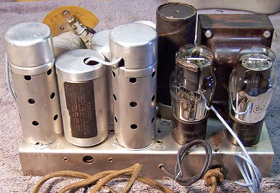
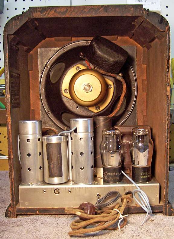
Atwater Kent Model 184 Restoration
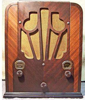 |
The Atwater Kent Model 184 is a small 4-tube AC superhet circuit radio.
It receives the standard broadcast band only. It uses a very unusual
circuit which incorporates regeneration in the second detector in lieu of
a separate IF amplifier stage There is a regeneration control on the
back, just like mid-1920's sets! And yes, if set incorrectly, it
will squeal! When set correctly, the set is very sensitive for a 4
tube radio.
The set had seen minimal servicing in the past. Only one paper
capacitor and one resistor had been replaced, and replacement filter
capacitors had been tacked in below the chassis (the original filter
capacitor cans were still in place). That being the case, I decided to try and maintain the original top and bottom chassis appearance if
possible and reverse previous repairs to the extent
possible.
The schematic for the AK184 can be found on Nostalgia
Air. Any part numbers will refer to numbers on that schematic. |
My antique radio
restoration logs
Previous Repairs
-
The original filter capacitor cans were still in place, and
tubular electrolytics installed under the chassis.
-
Only one original Atwater Kent resistor and one wax-paper capacitors
had been replaced.
-
The power cord plug had
been replaced.
-
Deteriorated insulation on several wires, as well as the
crumbling insulation on filament shunt resistor R14 had been covered with
tape.
-
Only one tube, a type 42, was branded RCA-Cunningham, and
could have been original. The remainder were replacements.
Overview
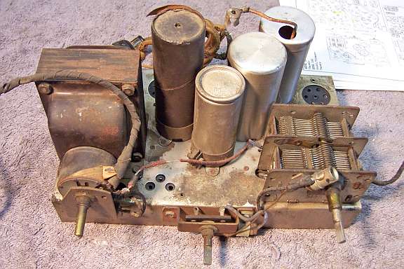
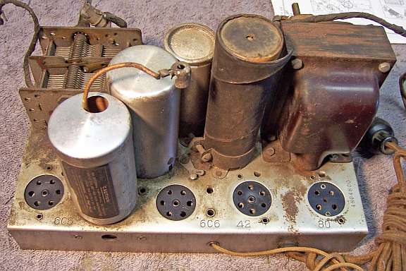
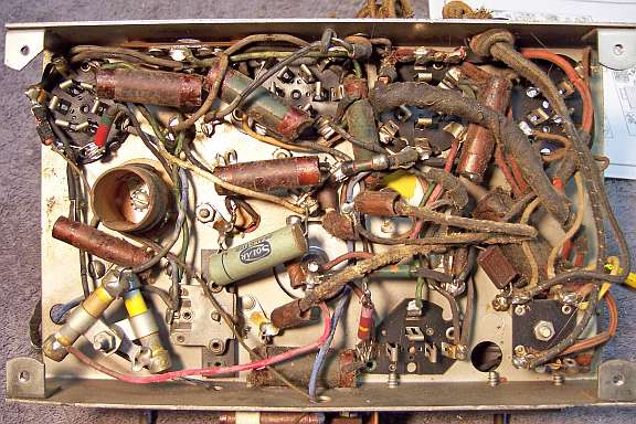
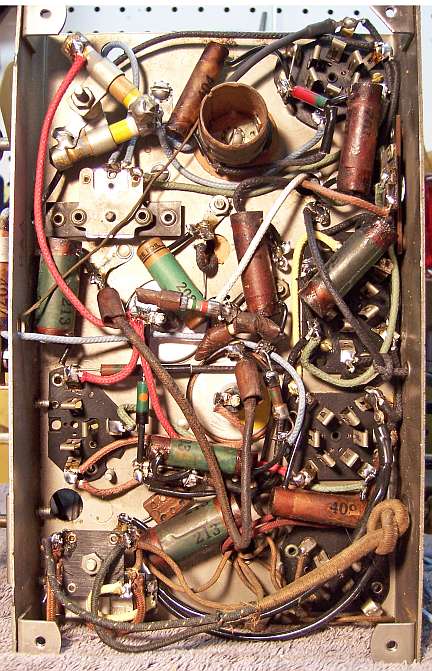
The chassis for this radio is very compact and is difficult to service. Some
components are buried beneath others that must be removed for access. Most
wiring was rubber covered and deteriorated - insulation would fall off if the
wire was moved even the slightest amount. The chassis was VERY dirty as
found:
Survey
My usual restoration procedure is to first make a complete
survey of the condition of all components. The survey results guide my
restoration strategy. If major and unique components are defective or
missing and
cannot be restored or replaced, I may elect to sell the radio rather than restore it.
I always assume that all paper and electrolytic capacitors are leaky and thus should be
replaced (I always "restuff" the original containers if possible).
Any mica capacitors are assumed OK until testing proves otherwise.
-
The AC power switch on the volume control was bad - dirty and/or oxidized contacts likely.
The control itself was OK after cleaning.
-
The speaker field and cone, output transformer, power transformer, and IF
transformer were good. The speaker field measured about 2000 ohms vs.
1000 ohms as documented in the Riders schematic. I have restored other
model 184's, and they had 1000 ohm field coils. This was a bit worrisome.
The speaker may have been replaced. For example, the speaker for the
earlier (and virtually identical) model 984 is about 2000 ohms!
-
The antenna coil and oscillator coil were OK.
-
Lots of rubber covered wire was bad - the insulation would crumble and fall
off if the wire was moved even a slight amount. Most of this wiring
would have to be replaced.
-
All resistors were in tolerance - rare indeed!
-
The original filter capacitor cans were still in place, and tubular filters
had been tacked in under the chassis.
-
The power cord was original, but had several breaks. The plug had been replaced.
-
The ground lead (black) had been
removed.
-
The tinfoil covered cardboard tube shields were missing, which is usual in
this model. In fact, I have only seen ONE set with original
shields. These were likely removed by servicemen to replace the
tubes. Since they have a wire soldered to the foil and to a chassis
ground lug, which has to be removed, they were likely NOT replaced.
Without these shields, the set will break into oscillation if the
regeneration control is advanced too far.
-
C7, 120pf mica, was defective (measured only about 50pf).
-
R5 (1 meg) had been replaced by a 250K resistor.
-
C4 had been replaced.
Repairs
All tubes were removed. Before starting repairs, I took photos of the chassis
top and bottom so that routing of wiring and component placement could be restored.
Lead dress is often critical in radios. Components were identified and
marked on the photo with a red felt-tip pen. I then removed all capacitors, documenting their locations
and connections. Some resistors were also removed for access. The
original filter capacitor cans were removed for rebuilding and chassis
access. The volume control and tone switch was removed for access
and for cleaning. The tuning capacitor was
removed for cleaning access to the chassis. The antenna coil T1 and IF
transformer T3, along with their shields, were removed for cleaning and for lead
wire replacement.
When I replace a resistor or capacitor, I
always remove the original part completely from a terminal. Other
components connected at the terminal are protected from heat using old medical
clamps. Excess solder is then removed using a solder sucker in order to
expose terminal holes for reattachment of the rebuilt or replaced component.
The top of the chassis was cleaned with GoJo hand cleaner and 00 steel
wool. The tuning capacitor was cleaned in an old Heathkit ultrasonic
cleaner with dilute ammonia. After drying, the bearings were lubed with
distributor cam lubricant. The dial drive reduction mechanism was removed,
disassembled, cleaned, and relubed using automobile distributor cam lubricant.
The original power cord was shortened in order to avoid breaks and
fraying. An old style bakelite plug was attached.
The power switch on the volume control was flooded from the front with Big
Bath cleaner and the switch cycled. It eventually worked OK. I was
NOT able to remove the cardboard rear cover in order to properly service the
switch (it was stuck to the volume control, and attempting to remove it would
have likely destroyed it).
Tube Shields
The original tinfoil covered cardboard tube shields were missing, which is
usual. Here are what the originals looked like:

Repeated Want To Buy postings on the Antique
Radio Forums Classified resulted in no hits for original replacement
shields. In previous restorations of this model, I installed Goat
type metal shields on the two 6C6 tubes, with a wire soldered to the shield and
to the extant chassis ground lug. This time I decided to try something
different. I first tried to reproduce the shields using cardboard tubing
and aluminum foil. The results were not satisfactory, as the foil tends to
wrinkle, and I was unable to find the correct thickness of cardboard
tubing. I had in my parts stock two covered tube shields along with their
shield bases, so I decided to install these shields. In the case of the
6C6 First Detector, the rivet holes for the tube socket matched the shield base
exactly. But not so for the 6C6 Second Detector - it had a much larger
socket for some reason. So I drilled holes through the chassis as well as
the socket (between pin connections) for the tube shield base. The shield
bases were installed using 4-36 hardware. The screws were installed on the
bottom (tube socket side), and small nuts on the top (tube shield base
side). Any excess screw length was cut off using a Dremel cut off tool.
Resistors and Capacitors
All the original Atwater Kent paper capacitors were rebuilt in their original cases
using modern 630 volt film capacitors in order to maintain the original
under-chassis appearance. I reseal the cardboard tubes using rosin
salvaged from RCA catacombs (it melts at a low temperature and will not damage
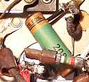
the replacement capacitors). I did not have an exact replacement for
the missing type 208 (.05mfd) AK capacitor, so I fabricated one using an old
Sprague cardboard tube and fabricated a label using Microsoft Word. The
Sprague tube was restuffed and the label glued on.
|
Reproduction Cap |
Original AK Cap |
 |
 |
The original filter capacitors cans (wet type) were rebuilt using new
parts. C14 (10mfd/475 volts) was rebuilt using a 10mfd/450 volt tubular
electrolytic. C13 (16mfd/300 volts) was rebuilt using a 22mfd/450 volt
tubular. The cans were scored deeply
about 1" up from their base on my Unimat lathe, and then cut in two using a
hobby razor saw. The positive electrodes were then removed, retaining the
stud. The flat portion of the stud was cut off short and a hole drilled for a screw, nut, and
solder lug. The replacement electrolytic capacitor was then connected to the solder
lug. The negative lead, extended with bare buss wire and with insulating
sleeving, was routed through a small hole drilled in the base. C14 was
covered by a cardboard insulator. In this case, the upper part of the
capacitor was not reused - only the base section was reinserted into the cover,
which was then retained by a clamp on the chassis. The two halves of C13
were rejoined using a PVC plumbing coupling, and secured with epoxy cement.
I normally test mica capacitors if one lead has to be disconnected
anyway. C7 (120pf) was tested and was bad - it measured only about
50pf. It was replaced with a very similar in appearance 100pf unit.
The insulation on the filament shunt resistor R14 was crumbling and falling
off. Someone had wrapped it with friction tape! The resistance wire
was OK. The center tap lug was first uncrimped and the resistance wire
removed. The rivet was drilled out and excess solder removed. Two
layers of spaghetti tubing (small and large) were then placed on both legs of
the resistance wire. The terminal ends were insulated using heat shrink
tubing. The two ends of the resistance wire were then twisted and secured
using a small 4-40 screw and nut through the center tap lug. Again, heat
shrink tubing was used to cover the repair and insulate the terminal lug.
Wiring Error, or Design Change?
When C8 was removed for restuffing, I noticed that it was NOT connected per
the schematic. It was connected directly from the plate of the second
detector 6C6 tube to the grid of the 42 output tube. In the schematic, it
should connect to the junction of R4 and R6. I assumed that the purpose of
R4 is to provide a voltage drop and regenerative feedback voltage through the
regeneration control A5 to the "tickler" winding on the IF transformer
T3. If C8 were connected directly to the detector plate, the feedback
voltage would be reduced due to the shunting effect of C8, C10 (when bass tone
is selected), R10, and the grid of the 42 output tube. C8 was original,
and there was no evidence of it having being moved. The parts placement
diagram supports the schematic. I'm wondering if this reduction in
feedback voltage was ON PURPOSE and a design change. Perhaps there were
complaints from customers that the radio was too unstable if setup as
designed. I have found that one must connect the antenna and ground and
THEN adjust the regeneration control. If the antenna or ground is changed
in any way, the set may break into oscillation. I restored the set per the
original schematic.
One other model 184 I restored was wired per the schematic, as was a model
984 I restored.
Wiring
Most of the original rubber covered wiring had to be replaced. The
insulation would crumble and fall off if the wiring was moved even the slightest
amount.
Testing and Alignment
Once the radio was reassembled and the tubes installed, power was brought up
slowly using a variac. AC power consumption was monitored using a watt meter, and a
DVM monitored the B+. The radio came alive immediately and worked. The set was then aligned - no surprises. The
radio worked well and picked up lots of stations using only a 20' piece of wire
in my basement. The radio is VERY sensitive, and especially for a 4-tube
set.
The B+ was about 246 volts - spec was 225 volts. But line voltage here
is quite high, about 122 volts, and the radio was originally designed for 115
volts. But obviously the 2000 ohm speaker field worked fine and did not
reduce the B+. Perhaps the schematic was incorrect! I did not think
to measure the voltage drop across the field before reinstalling the radio in it
cabinet. That would have provided a good cross check (schematic says the
B+ drop is 55 volts).
Restoration Results
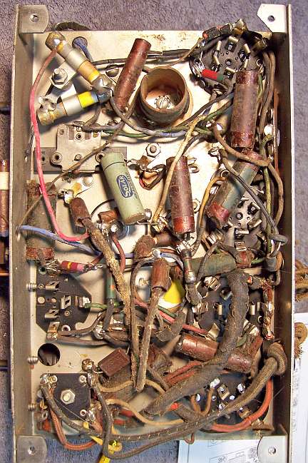
Chassis Before
|
Chassis After
|
 |
 |

