Emerson Model Q157 Clockette Restoration
 |
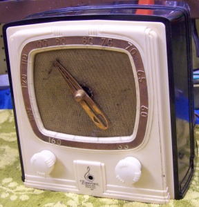
The Emerson model Q157 from 1937 is a small 4-tube AC/DC TRF
circuit radio with a Plaskon case. The front of the radio
resembles a clock face, and is sometimes called the "Clockette"
(perhaps wrongly so, as this term is normally applied to the Kadette K25
Clockette). The radio had seen some servicing in the
past. Several parts had been changed.
The radio's circuit is very similar to the many low-cost "depression" sets of the early to mid 1930's, except that this
radio used an octal 25L6G tube instead of the usual type 43 output
tube. I suspect the 25L6G was used simply because it has a smaller
envelope (this is a VERY compact set).
The schematic is available on line at Nostalgia
Air. Any part number references will be relative to that
schematic. |
My
antique radio restoration logs
Condition as Found
The radio was purchased in the flea market at the Charlotte AWA Radio Conference in
2012. As acquired, the Plaskon case had no obvious cracks or breaks. Later, I
found that the dial pointer was not original, and that there was a small
hairline crack. The metal screen over the
speaker had some damage and staining, but was acceptable. The resistance
line cord ("Curtain Burner") had been wrapped with what looked like
white coiled telephone cord! A phono jack was dangling from a piece of zip
cord connected to the radio. The knobs were present and were original.
There was one cabinet foot missing and one extant foot was missing its spacer.
Survey
My usual restoration procedure is to first make a complete
survey of the condition of all components before starting any repairs. The survey results guide my
restoration strategy. If major and unique components are defective and
cannot be restored or replaced, I may elect to sell the radio for parts rather than
to restore it.
I assume that all paper and electrolytic capacitors are leaky and thus should be
replaced (I always "restuff" the original containers if possible).
Any mica capacitors are assumed good until testing proves otherwise.
-
The dial pointer was not original. I obtained an
original pointer from David Frush, but when checking its fit, discovered
that the plastic stud that holds the pointer had been broken off! This was
a potential showstopper!
-
A phono input jack had been installed. Fortunately, it had
been installed at the end of a short piece of AC zipcord - no holes had been
drilled into the cabinet or chassis. The cord was
connected between the chassis and PLATE of the 6C6 detector tube. I'm
not sure how well this would have worked. And in addition, this is a
HOT CHASSIS radio, so the phono hardware could have been a shock hazard. And
this connection method would have placed B+ voltage on the phono cartridge (through
a 500K resistor) with no isolating capacitor (unless one was installed in
the phonograph).
-
The 25L6 cathode resistor R8 (110 ohms, 1/2 watt wire wound)
had been replaced by a 150 ohm 10 watt resistor, and a small electrolytic
capacitor was placed in parallel (I suppose to increase the gain of the
output stage for the phono function).
-
The original filter capacitor had been replaced. All
other capacitors and carbon resistors were original.
-
The speaker field coil, cone, and output transformer were
OK.
-
Both RF coils were OK.
-
Almost all resistors were out of acceptable tolerance range
(+/-20%). There was
one wire-wound metal clad resistor (the pilot lamp shunt R10) that measured 52
ohms (should be 40 ohms). The smaller carbon resistors were an older
style that were the size of modern 1 watt carbon composition resistors.
-
It was assumed that all paper-wax capacitors would be
leaky. There was also a molded 0.1mfd 400 volt capacitor used as the
AC line bypass (brand was Solar). It was measured and was leaky.
-
One cabinet foot was missing. A spacer was missing
from another foot. The feet are threaded and actually hold the cabinet
and chassis together.
-
The cardboard speaker surround was damaged and in several
pieces, but all parts were present.
-
The dial drive cord was OK.
-
The pilot lamp was OK.
-
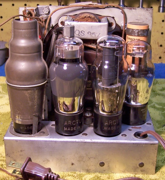
All the tubes were branded Arcturus, and were likely the
originals. All except the 25Z5 were good. The 25Z5 tested bad on
one side and also indicated a short.
Repairs
Dial Pointer
The original dial pointer was attached to a stepped stud on a plastic pulley which
was driven by a cord from the tuning capacitor and tuning knob. The tip of
the stud was broken off, and the original pointer had been replaced by one that did not
require the stud. I was able to obtain an
original pointer, but needed to find a way to attach it to the pulley. The
diameter of the stud needed was about 5/32"+ inches. I found a steel rod in my junk parts
stock which
was a suitable size. The plastic pulley was removed
from the radio and carefully chucked into my small Unimat lathe. The end of the
remaining stud (larger diameter portion) was cleaned up and filed flat. A
center drill in the lathe tailstock was used to precisely locate the center of the stud. A
suitable hole was then drilled into the pulley while still mounted in the
lathe. It is VERY important that the stud be exactly centered. A
1/2" piece of the steel rod was then inserted into the pulley - held only by
friction. The dial pointer could then be installed onto the steel rod and
secured by a set screw in the pointer.
Line Cord Resistor
The original line cord resistor R9 (185 ohms, 17 watts) was severely damaged
and not usable. In order to reduce the heat that would be dissipated
inside the cabinet if an equivalent resistor were installed, I decided to use a
diode to reduce the line voltage to the filaments. A diode in series with
the tube filaments will
reduce the voltage by a factor of 0.707, or to about 85 volts. The tube
filaments and pilot lamp together require 68.6 volts. This means that only
about 17 volts needs to be dropped, at 300ma. Thus an additional 59 ohms resistance is needed. The power dissipation is only 5.1 watts as
compared to 17 watts without the diode. Only a 10 watt resistor would be
needed. Checking my stock of power resistors, I decided to use two 130 ohm
5 watt resistors in parallel. I did not have a 60 ohm 10 watt resistor in
stock, and did not wish to pay shipping for a single item at Mouser! Also,
there was really no space under the chassis for a 10 watt resistor, but plenty
of space for two 5-watt units stacked on top of each other. Of course, the presence of the diode meant that the radio would no longer work
on DC (but today, that is not an issue).
Capacitors
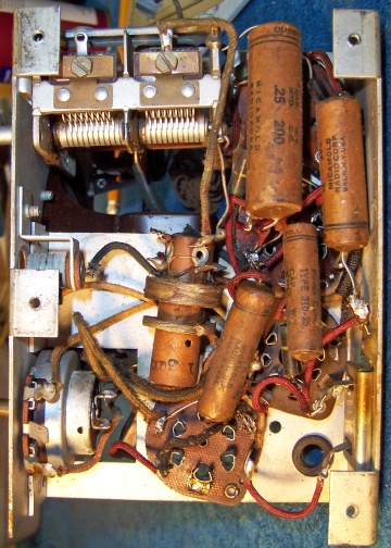
All five original paper-wax capacitors (called "roll" capacitors in
the parts list) were restuffed with new metal film 630
volt axial capacitors in order to maintain the original under-chassis
appearance. I reseal the cardboard tubes using rosin salvaged from RCA
catacombs (it melts at a low temperature and will not damage the replacement
capacitors). All "roll" capacitors were Micamold branded. The Solar brand bakelite molded line bypass capacitor (0.1mfd 400 volts) was
also rebuilt. The case was sliced open using a Dremel cut-off
disc and a hobby razor saw. The contents were removed, and a 0.47mfd 400
volt radial film capacitor was installed inside - it would just fit inside the
case (the only capacitor in my stock that would fit). The case was then reassembled using epoxy. The original
appearance was thus maintained, although the slice in the case is visible (I made no
attempt to conceal it). I made careful notes of the original capacitor lead lengths used and any insulation
sleeving (almost every capacitor had red spaghetti tubing installed to prevent
shorts, since the chassis was very cramped and compact).
Evidence on the chassis indicated that the original filter capacitor was
likely a tubular clamp mounted unit with wire leads. There was an unused
hole on the right front side of the metal front plate holding the speaker, near
the top, and signs that something had been mounted there. There was almost
no other space on the chassis for a filter capacitor. The original
capacitor was listed as a dual 16 mfd unit at 100 volts (likely a mistake in the
Riders schematic - it would have to be at least 150 volts).
 |
I found a dud
capacitor in my dud stocks that was clamp mounted. I restuffed it using
two 22mfd 160 volt capacitors, adding wire leads. I then fabricated a new
label with the Emerson part numbers and original values. The clamp was
then reattached and secured to the capacitor with a small screw (the original
rivet was drilled out in order to remove and relocate the clamp). The
capacitor was then mounted on the front panel using the clamp and a screw that
protruded from the speaker mounting - the likely original mounting hole was not
used. |
Resistors
The metal clad pilot lamp shunt resistor R10 measured 52 ohms - spec was 40
ohms. I decided to leave this resistor in place pending completion of
testing (the original pilot lamp was OK). Once the radio was restored and
tested, I felt that the pilot lamp was MUCH too bright at power on, and would
soon fail. So I added a shunt resistor (hidden in sleeving) to bring the
resistance down to the 40 ohm specification (I used 160 ohms, 1/2 watt).
The lamp is still too bright at turn on, IMHO. The simple 40 ohm shunt
does not provide the soft start function common with later sets that use a 35Z5
rectifier (which has a pilot lamp filament tap).
I had nothing in my resistor
stocks that looked anything like the carbon resistors used. They were rated 1/4 watt, but were the size of modern 1 watt carbon composition
resistors. I decided to use modern 1-watt carbon resistors but
to paint them to resemble the original resistors using hobby enamel paint.
Originally there
were several coding schemes used on the various resistors. I decided to repaint the
replacements using the scheme of the only good original resistor left in place: body,
end, stripe for the first two digits of the value and the multiplier. For
example, 2 megohms would be red (body), black (end), and green (stripe).
R8 (110 ohms, 1/2 watt, wire wound) had been replaced by a 150 ohm 10 watt
resistor. Since this resistor had been
replaced, I had no ideal what the original looked like. But it was likely
a flexible type wire wound resistor, which are usually rated 1/2 watt. I
had no suitable flexible wire wound resistor in stock, so I used a small
wire wound resistor that measured 101 ohms which already had an insulating sleeve
covering it, thus resembling a flexible resistor.
Other Repairs
- Cabinet feet and spacers: I was missing one cabinet foot and two brass spacers. I
was able to obtain a missing cabinet foot from David Frush, but he did not have any
of the brass spacers in stock. I decided to use wooden spacers I had
in stock. They were the correct diameter, and were cut to
length. They were then painted with Aged Brass enamel paint to resemble
the originals.
- Speaker surround: The cardboard speaker surround had been damaged
and broken in
a couple of places. It was repaired using shirt cardboard and GC
Service Cement.
- Since this radio has a "hot chassis", some minor changes were
made to improve safety and reduce the risk of a shock hazard. A
polarized cord set was installed. The lead that was connected to the
wide blade of the plug (neutral) was connected to the chassis. The
other lead ("hot") was routed through the AC switch and then on to
the rectifier and filament string. The original radio would have had a
hot chassis when either ON or OFF (depending on which direction the plug was
inserted).
- The cabinet was cleaned using GoJo white hand cleaner, 00 steel wool, and
old toothbrushes.
- The pilot lamp bulb was stained green using Vitrea 160 Emerald stain glass
dye.
Testing
After completion of restoration, the radio was connected through a watt meter
to a variac and the power gradually applied while monitoring the B+. A 50'
indoor antenna was connected. The radio worked immediately, and
picked up lots of stations using only my indoor 50' antenna strung across the
basement ceiling. The radio was then aligned. There are only two
trimmers on the tuning capacitor. These were peaked when tuned to a
station at the high end of the dial. While the radio works very well,
it does require a longer than usual warm-up time, like due to the filament
dropper resistor being slightly larger than ideal (66 ohms vs. 59 ohms).
Post Restoration Photos
 |
 |
|
Chassis Before Restoration |
Chassis After Restoration |


