Silvertone 7085 Wire Recorder
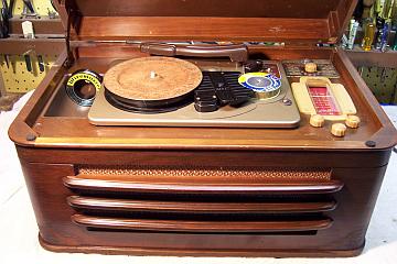 |
The Silvertone 7085 is a combination radio, phonograph, and
wire recorder. It is circa 1947 and is the cabinet or table top
model (there is also a console model). It has eight tubes. It can
be a normal radio or 78RPM record player. It can both play and
record on recording wire from the radio, phonograph, or from an included
microphone. The radio is nothing special - basically an AA5 using
Loctal tubes. It has a built in loop antenna, and will also accept
an external antenna. The three additional tubes are used for the wire
playback head preamp, the recording bias oscillator, and a second
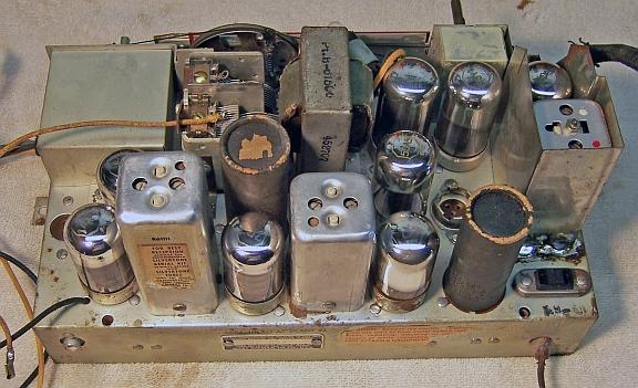
rectifier tubes. The radio had seen minimal servicing in the past -
most of the original parts were still in place - only two small capacitors
had been replaced.
The schematic for the Silvertone 7085 (chassis 101.814) can be found on
Nostalgia
Air (under model 8085).
|
My
antique radio restoration logs
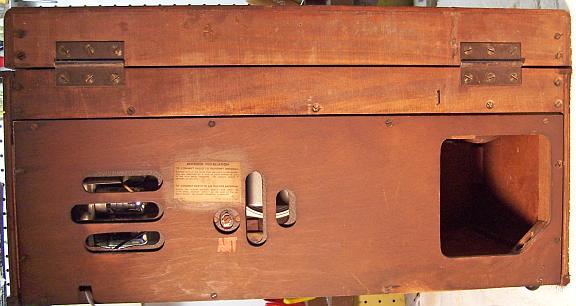
Condition As Found
This unit was purchased on eBay. Even though they are
large and complex, they do not go for much money. Unrestored units
typically run $60 to $100, but of course are expensive to correctly ship!
My unit was complete with all knobs and the
back cover/loop antenna. Two spools of recording wire were included (used -
interesting to see what was recorded!). The original microphone and its
base was present. The phonograph cartridge and needle was present, but
crystal cartridges last only a few years and thus it was assumed to be bad.
The unit had been invaded by mice at some point in its past
judging from the existence of nesting materials (newspaper). They had
chewed some wires and cables, but mostly the cloth sheaths on the phonograph
pickup lead and transfer switch cables. The chassis had some rust or
corrosion due to their urine, and the speaker frame was severely corroded! As found, the motor would run, but the none
of the rotating parts functioned. I assumed this was due to caked-on
lubrication and/or bad idler wheels. The cabinet was in presentable
condition, but appeared to have suffered some water damage in the past (two
stains and finish loss on the bottom front corners. I
did not test the radio, since I do not normally apply power until the radio has been
examined, tubes tested, and capacitors replaced.
Previous Repairs
Two small capacitors had been replaced. All the rest
looked original. Not all tubes were Silvertone brand, so I assumed that
some had been replaced.
Survey
My usual restoration procedure is to first make a complete
survey of the condition of all components. The survey results guide my
restoration strategy. If major and unique components are defective or
missing and
cannot be restored or replaced, I may elect to sell the item rather than restore it.
I always assume that all paper and electrolytic capacitors are leaky and thus should be
replaced.
-
The dial cord was broken
-
The phonograph motor ran, but the turntable/take-up reel and supply reel
would not rotate
-
The AC power switch was bad (it measured high resistance) - dirty and/or oxidized contacts
were likely.
-
The power cord looked original and in good condition
-
Two wax-paper capacitors had been replaced - all other capacitors were
original.
-
Insulation on the shielded phonograph pickup lead and transfer switch
leads had been chewed by mice. The speaker leads had also been chewed.
-
The crystal microphone was dead - no output.
-
The phonograph cartridge was dead - no output.
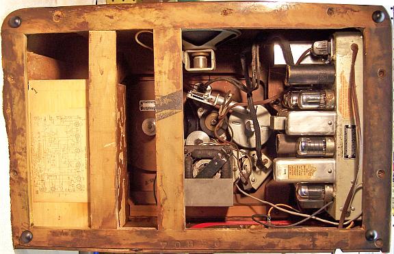
-
All coils and transformers were OK.
-
The speaker frame was badly rusted.
-
Both 35Y4 rectifier tubes were bad - one had an open filament, the other
tube tested as shorted. All other tubes tested good, including the rare type
1280 preamp tube.
-
The pilot lamp bulb was burned out.
-
The phonograph motor slide switch (part of the function switch assembly) was
sticking.
-
10 resistors were out of tolerance. One 25 ohm wire wound resistor was
open.
-
There was a missing spring in the wire recorder transport
mechanism.
Repairs
Before starting restoration, I had to make sure that the phonograph/wire
recorder transport mechanism could be made to work at reasonable cost. At
least the motor ran, but the turntable (which doubles as the wire take-up reel)
and wire supply reel did not turn when the function switch was moved. I initially assumed that this was due to caked-up lubrication and/or
bad rubber tire idler wheels (it had THREE idler wheels). After some
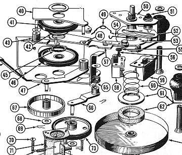
disassembly, I found that a torsion spring was missing in the mechanism. This
spring (part 49 in the diagram below) links the function switch to a lever that
shifts the idler wheels from the turntable (play mode) to the supply reel
(rewind mode). I made several attempts to reproduce this part from my
collection of springs. After several attempts, I made one that "sort
of" worked. The turntable would rotate and pull wire from the supply
reel in PLAY mode, but there was not enough torque on the take-up reel in REWIND
mode. At this point I was convinced that I would have to find a
replacement spring.
I picked up an old Crescent Model H-22A1 wire recorder a the Charlotte AWA Conference (it was in
the free pile, since its case had been eaten by termites!). I was hoping that it
would supply the missing spring. But alas, even though the mechanism
looked identical to my Silvertone from the top, this unit was push button/solenoid operated, and it did not have the missing spring. I also contacted a seller on eBay who
restores and sells wire recorders. He told me that this particular spring
is often missing or broken in the units he restores. He makes up his own
springs, a complex process involving heat treatment afterward. I could
have purchased a complete mechanism from him, but the cost would have been
double what I paid for my entire unit, and the mechanism was a different part
number and designed for a different radio chassis. He did supply me with a parts list for the Silvertone, so I would
at least learn what the spring looked like. I next contacted West-Tech
Services, who repairs these units, and asked if they could supply the
part. They were able to come up with the
missing spring. But it was very expensive ($50 with shipping) likely due
to the cost of labor to disassemble a unit. And to make matters worse,
the spring they supplied was not original - it did not work any better than my
reproduction. I assumed that since the spring supplied by West-Tech
Services was removed from a working unit, there must be something else wrong
with my mechanism.
I found that with my spring installed, the turntable/take-up spool worked as
it should. But in rewind mode, the supply wheel did not provide enough
torque. Since the idler shifter was apparently working properly, I now
began to suspect the idler wheel that drives the supply reel. Just like
with phonographs, the rubber tire will harden with age and begin slipping.
I then again looked at the parts in my junker Crescent wire recorder. But the
pulley (part 73) and lever (part 66) were ever so slightly different than the
corresponding parts in the Silvertone, and the
bushing was too small to fit over the corresponding stud. But the idler
wheel in the Crescent was in excellent condition. With nothing to lose, I enlarged the
hole in the lever (part 66) so that it would fit over the stud in my unit.
I did this using a series of drill bits in my drill press, and finished using a
small round file. Once this idler and lever was installed, the mechanism
worked properly in all modes, and would properly rewind a reel of wire. Of
course, at this point I did not know if it ran at the correct speed. But
now that the mechanism could be repaired, I proceeded with the remainder of the restoration. The
transport mechanism was
then completely disassembled and all parts cleaned and lubricated before reassembly.
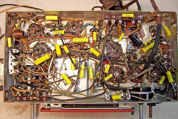
At this point I made BEFORE photos of the radio chassis top and bottom. I use these photos to ensure that replacement parts and
wiring are placed as close as possible to their original position. Some
radios are subject to problems (such as oscillation) if wiring is re-routed or
lead dress is not the same as the original..
The top and sides of the chassis were cleaned with GoJo hand cleaner and 00 steel
wool. Since this process may leave small steel wool fragments that can cause
problems later, I follow up with a thorough vacuuming and go over everything
with a small magnet and masking tape to pick up any stray fragments.
The power switch on the tone control was flooded with Big Bath cleaner/degreaser
through a small opening in the control. After the switch was cycled many
times, it worked well. The sticking spring-loaded slide switch which was
part of the function switch assembly was removed, disassembled, cleaned and
lubricated. While apart, the contacts were also cleaned. After
reassembly, it still did not operate reliably - still sticking. I determined that the
return spring was not providing enough tension. It was stretched slightly
and reassembled. After this, the switch worked as it should.
All 26 paper-wax capacitors in the radio chassis were replaced using modern 630 volt
axial film
capacitors. I chose not to restuff the original capacitors in this unit,
since it is not a particularly valuable item, and about half the capacitors were
Sealtite solid wax caps that cannot be restuffed. The 10 out-of-tolerance resistors were replaced from my stock
of NOS carbon composition and film resistors. One 25 ohm 1 watt wire wound
resistor (surge limiter from the cathode of one of the rectifiers) was open. I replaced
it with a 22 ohm 1 watt carbon resistor. The radio chassis has two can
type metal twist lock capacitors. Both were rebuilt in their original
cans, and the original terminals retained. This way, the original wire and
component routing could be used. There is hardly any room under the chassis to
install terminal strips and new tubular electrolytics. The 40+40mfd@200
volt unit was rebuilt using 47mfd@250 volt radial capacitors. The
40+40@150, 20mfd@25 volt unit was rebuilt using two 47mfd@160 volt radial
capacitors and
a 22mfd@50 volt capacitor. Both units had cardboard sleeves which were replaced
(but not glued, in case they need to be removed later for servicing). My restuffing process
for twist lock capacitors is as follows:
- Before removal from the chassis, the orientation of the capacitor was
noted.
- All components and wiring was removed from the terminals and
ground/mounting lugs.
- The mounting lugs were cleaned up and straightened to enable removal of
the capacitor without damaging the fiber mounting insulator.
- The crimp around the base was uncrimped using a variety of tools
- The terminal board and gasket was removed after the aluminum connecting the
terminals to the body of the capacitor were cut.
- The old contents were removed by applying a heat gun to melt the tar which
retained it (in cases where the contents cannot be removed this way, I use a
3/4" spade bit and drill out the majority of the material then dig out
the rest using screwdrivers).
- The old can was cleaned out.
- Holes were drilled through the fiber backer and terminal board close to
the terminals.
- The new components were installed inside the old can. Leads for the
common ground and positive leads were routed through the drilled holes and
attached to the original terminals. The ground or common lead
was routed through the terminal board near one of the mounting lugs.
- The terminal board and gasket was reinstalled and the crimp on the base
restored.
- The original cardboard sleeves were reinstalled.
- Once mounted in the original position, the mounting lugs were twisted to
retain the capacitor. The common ground lead was then soldered to one
of the mounting lugs.
Several wires that had been chewed by mice were replaced. The volume
control and tone control were each given a shot of Big Bath cleaner and cycled. The
function switch was also cleaned using Big Bath spray and operated repeatedly.
Two used/tested 35Y4 tubes were installed. The remainder of the tubes were
good and were reinstalled after cleaning.
I decided that I could not live with the rusty speaker, even though it
apparently worked OK. My junker Crescent wire recorder used a similar speaker. It
was the same diameter and voice coil impedance and the mounting holes were the
same. But it had an output
transformer riveted to the frame. The original speaker had a 3-pin plug
installed which mated with the speaker cable from the chassis. I drilled out the rivets and
removed the transformer. I then moved the original speaker plug to the
replacement speaker. The original speaker cable had been chewed by mice,
and had to be replaced anyway.
Cabinet
The cabinet was thoroughly vacuumed and then cleaned with GoJo hand cleaner
and steel wool.
Testing and Alignment
Once the radio chassis was reassembled and the tubes installed, power was brought up
slowly using a variac. AC power consumption was monitored using a watt meter, and a
DVM monitored the two B+ sources. The radio worked immediately. The radio was
then aligned. The performance is nothing to brag about - it is really just
a normal AA5 circuit using Loctal tubes and an unshielded loop antenna.
The wire recorder function was first tested using the used reels that came
with the machine. It was found that playback worked well, and it appeared
that the unit was operating at the correct speed. One recording was
excerpts from Handel's "Messiah" recorded from a radio broadcast,
probably in the 1950's. I then attempted to record from the radio to the
reel. That function ALSO worked! I was not able to test recording
from the microphone, since the microphone was dead. And the phono
cartridge was also dead. At this writing, I have not decided to restore
these units, as the cost is considerable. West-Tech Services charges $60 to
restore a crystal microphone, however replacement elements are often available
on eBay for as little as $10. However, these may not fit in the microphone
case without modifications. West-Tech also sells replacements for the Astatic
L-71-A crystal cartridge and stylus, as do other companies on the Web.
There is considerable information on wire recorders on the web. I found
several interesting sites:
Operating Instructions
Great information and lots of
additional Wire Recorder links
Video Exchange Transfer Service - Transfer service from wire recording to CD
and other media.
Restoration Results

Chassis After Restoration