The schematic for the Stewart-Warner R-180-A can be found on Nostalgia Air. Any part numbers will refer to numbers on that schematic.
|
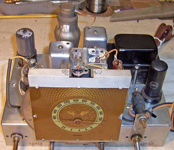
The Stewart-Warner Model R-180-A (chassis R-1802-A) from
1938 is a large five tube AC (transformer
type) table
radio. It receives the broadcast band and one short wave band. The radio had seen
minimal servicing in the past, and most of the original parts were still
in place. I decided to try to reverse any previous
repairs to the extent possible and to restore operation.
The schematic for the Stewart-Warner R-180-A can be found on Nostalgia Air. Any part numbers will refer to numbers on that schematic. |
My antique radio restoration logs
This radio was purchased on eBay. It was sold as not tested. The power cord was extremely worn and not safe to plug in (which may have saved the radio from destruction!) My example cabinet was presentable, with the usual scratches, wear and dings. It had all its original knobs and grille cloth, and the cloth was in good condition. The radio originally used all G type octal tubes. While the parts count is not high for this radio, the chassis is quite cramped and difficult to work on. Access to some parts that must be removed for servicing is difficult.
The radio had seen some repairs in the past. It is not known if these repairs were done by service techs or by a collector.
Most if not all the tubes had been replaced. Two G type tubes were still installed (6Q7G and 6U7G, which were branded Ken-Rad and Crosley/Ken-Rad). I'm not sure what brand of tubes were original to the set. Another Stewart-Warner radio I restored had its original tubes in place, and they were all branded Acturus. 6A8 and 5W4 metal tubes, and a 6K6GT were installed, which were replacements for sure
The volume control had been replaced.
One wax/paper capacitor (part 5) had been replaced.
A Miller ferrite rod type antenna had been installed. It would not have worked as wired, since it was only connected to the antenna and ground connections. The instruction sheet was inside the radio. This accessory was intended to replace the radio's existing antenna coil, and thus eliminate the need for an outside antenna wire.
My usual restoration procedure is to first make a complete survey of the condition of all components. The survey results guide my restoration strategy. If major and unique components are defective or missing and cannot be restored or replaced, I may elect to sell or keep the radio for parts rather than to restore it. I always assume that all paper and electrolytic capacitors are leaky and thus should be replaced (I always "restuff" the original containers if possible). Any mica capacitors are assumed OK until testing proves otherwise.
The power transformer was OK. The high voltage was balanced across the center tap with 20 volts applied to the primary through a variac. With full power applied (no tubes present), the wattage consumed was less than 10 watts. A transformer with shorted turns will draw excessive power and will heat up. I use a real analog watt meter for these tests. I always check for shorted turns before starting a restoration, since it may take some time before a transformer shows signs of overheating (after the owner has gone to the trouble and expense of replacing all capacitors or even investing in replacement tubes).
The antenna coil and oscillator coil were OK.
The IF transformers were OK.
The output transformer primary winding was open. This was likely caused by capacitor 11 (.004mfd/750 volts) shorting. The capacitor showed signs of distress when removed! This capacitor connects between the 6K6 output tube plate and ground. So a short in this part would result in full B+ across the output transformer primary, This is likely what killed the radio.
The speaker field coil was OK. The speaker cone was distorted and out of shape, and the voice coil was jammed between the pole piece and frame. It was not obvious how this happened, since the grille cloth was original and not damaged. It looked like water damage, although there was dry dust around the edge of the cone and no water damage to the cabinet or grille cloth.
All resistors, including the wire wound resistors, were in tolerance!
The power cord was in very bad condition.
The pilot lamp was burned out.
The rubber grommets supporting the tuning capacitor were hardened and in pieces.
The 6A8 tube was weak (not original).
The damaged speaker cone was a potential showstopper to restoration. This issue had to be resolved before investing any time or money in this radio. To have the speaker re-coned would have cost $60+ including two-way shipping. And a replacement field coil speaker which was the correct size and field coil resistance would be difficult to find. I had nothing suitable in my parts stocks - either field coil or permanent magnet types. Having nothing to lose, I decided to try a trick I had read about on the Antique Radio Forums. Using a foam brush, I wetted down the entire front of the cone (except the voice coil area) with water. Once one side of the cone was moist (the back side was largely not accessible), I attempted to straighten out the cone. Incredibly this worked - the cone popped back into shape. The cone then moved freely in and out and did not appear to be dragging on the pole piece. There were also some cracks and breaks in the cone - but no holes. These were bridged using several layers of GC Service Cement.
I also had to find a suitable replacement audio output transformer. The problem was to find one (a universal type) that would fit in the available space. The original transformer was mounted under the chassis and surrounded by other parts. There was plenty of space on top of the chassis, but I wanted to keep the radio as close to original as possible. I decided to use a Stancor A-3856 universal 3 watt output transformer. It would just barely fit in the available space if one mounting hole was moved about 1/8". The voice coil measured 2.9 ohms DC resistance, so I assumed that the voice coil impedance was about 3.2 ohms. The 6K6 output tube expects a load impedance of 7600 ohms. The Stancor A-3856 will match those impedances fairly closely.
Since all showstoppers to restoration had now been resolved, I proceeded with the electronic restoration. All tubes were removed and dust was removed using an air compressor. Before starting repairs, I took photos of the chassis top and bottom so that routing of wiring and component placement could be restored. Lead dress is often critical in radios.
When I replace a component, I always remove the original part completely from a terminal. Other components such as mica capacitors and in-tolerance resistors connected at the terminal are protected from heat using old medical clamps (hemostats). Excess solder is then removed using a solder sucker in order to expose terminal holes for reattachment of the rebuilt or replaced component.
The tuning capacitor and dial assembly was removed for cleaning and for replacement of the rubber mounting grommets. The capacitor was cleaned in my old Heathkit ultrasonic cleaner using dilute ammonia. I then cleaned the capacitor using soap, water, and old tooth brushes. After a thorough rinsing and towel trying, the capacitor was dried using a heat gun. The bearings were then lubricated using automotive distributor cam lubricant.
The chassis top, front, back and sides was cleaned using GoJo (white) hand cleaner and 000 steel wool. Since the steel wool may leave small fragments behind that could cause shorts, I go over the cleaned chassis with a vacuum cleaner and magnets.
The original wax/paper capacitors were restuffed using new axial film capacitors. The originals were simple cardboard tubes sealed on both ends with tar (not wax). They were marked with values, voltage rating, and a part number which matched the schematic. They looked similar in appearance and construction to early GE/RCA capacitors. Here is how I normally restuff paper capacitors.
Capacitor C8 (.05mfd/200 volts, original part #88189) was a replacement. I replaced it using a vintage RCA/GE dud marked part #35149, which was cleaned out and restuffed. The dud looked similar to the other capacitors used in the radio. Part C11 (.004mfd/750 volts) was a problem. This was the part that had failed and destroyed the output transformer. I hesitated to restuff if with a 630 volt capacitor. And higher voltage capacitors were too large for the original case. So I decided to replace it with a .0039mfd 1000 volt capacitor rather than restuff the original case. The capacitor is mostly hidden by another capacitor on top of it.
The electrolytic capacitor C12 (10mfd/25 volts) was cleaned out and restuffed using a 22mfd/50 volt electrolytic. Its value is not critical, since it simply filters the bias supply voltage to the 6K6 output tube.
The filter capacitor C13A/B was originally a dual 8mfd/400 volt cardboard case capacitor with wire leads. The common lead in this case was POSITIVE rather than negative. The original capacitor was cleaned out (with difficulty) and restuffed using two 10mfd/450 volt electrolytic capacitors. The connections to the wire leads were insulated using spaghetti tubing. The two replacement capacitors were wrapped in strips of paper towel to center them in the case, then the capacitor was sealed using melted rosin salvaged from servicing RCA Radiola Superhet catacombs. New wire leads were attached. Here is the restuffed capacitor.

The cabinet was vacuumed and then cleaned using GoJo (the white type, not pumice) hand cleaner and 00 steel wool.
Once the radio was reassembled and the tubes installed, power was brought up slowly using a variac. A DVM monitored the B+. The radio came alive and worked on both bands. The radio seemed quite sensitive using my 30' indoor basement antenna, and we are in a rural area. The speaker sounded OK - no rattle or other problems were noticed.
Most of my restoration objectives were met, but not all. There was no intention of restoring the set to factory new appearance! My objective is usually to reverse any prior servicing and make the radio appear to have never been repaired. Here are some of the "misses":
Chassis Bottom Before Restoration |
 |
Chassis Bottom After Restoration |
 |