Truetone Model D911 Restoration
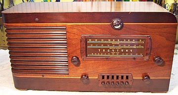 |
The Truetone Model D911 from 1942 is a large 8-tube AC wood horizontal tabletop radio that features push-pull output, a large Rola
electrodynamic speaker,
a tuning eye, and push-button or automatic tuning. It receives the
broadcast band and two short wave bands. Truetone radios were sold
by Western Auto Supply. |
| The set had seen minimal servicing in the past. The filter
capacitors had been replaced with very similar units, and four wax-paper
capacitors had been replaced. That being the case, I decided to try
to maintain the original top and bottom chassis appearance and to reverse
any previous repairs to the extent possible. |
The schematic for the Truetone D911 can be found on Nostalgia
Air. Any part numbers will refer to numbers on that schematic. |
My
antique radio restoration logs
Overview
This radio was purchased at the 2012 Antique Wireless
Association conference and flea market in Charlotte, NC. It appeared to be
in original condition with its original knobs and cabinet finish. There
were no breaks in the escutcheons - unusual since this type has cracks near the
mounting screw holes due to shrinkage. There were no signs of prior servicing obvious other than possibly the line
cord. The radio uses a very unusual mix of tubes! The converter and
second detector/AVC/1st audio were metal octal tubes. The rest were all
standard base (big pin) types, one with an original Goat shield (6D6). The
lineup was: 6K8, 6D6, 6Q7, 76, 41, 41, 80, 6G5! But since this set was
built right before the start of WWII, that could explain the parts selection -
likely some parts vendors were shutting down due to war production. The
radio was likely built by Detrola, and the build quality was very high.
While the set does not have an RF amplifier stage, it does have a tuned
pre-selector for the broadcast band (three gang tuning capacitor).
Previous Repairs
-
The original filter capacitors appear to have been replaced with
very similar types. The original nuts holding them were still soldered
to the chassis, so whatever was there had the same threads and mounting
style. The only hints as to their replacement were that the part numbers
on the units did not match the schematic, both stamped part numbers were the
same (the originals had different voltage ratings), and the wire leads were
much longer than necessary and were folded up under the chassis.
However, in one case the original could not have been any larger in diameter
than the
replacement, otherwise its case would have contacted the tuning shaft!
There is VERY little clearance. It is also not known if the originals
had a positive terminal lug or had lead wires.
-
Four original Solar Sealdtite paper capacitors had been
replaced.
-
One resistor had been replaced (with an incorrect value).
-
Most of the tubes were likely replacements.
-
The power cord had been replaced.
-
The tuning eye socket had been taken apart but not properly
reassembled. The one megohm 6G5 plate
load resistor normally inside the socket had been replaced by a 250K 1 watt resistor external to the
socket. (with electrical tape holding it to the cable).
Survey
My usual restoration procedure is to first make a complete
survey of the condition of all components. The survey results guide my
restoration strategy. If major and unique components are defective or
missing and
cannot be restored or replaced, I may elect to sell the radio rather than restore it.
I always assume that all paper and electrolytic capacitors are leaky and thus should be
replaced (I always "restuff" the original containers if possible).
Any mica capacitors are assumed OK until testing proves otherwise. I
never apply power to a radio before restoration, even using a variac or
"dim bulb" tester.
-
The large Rola speaker was in great condition, and its field
coil was OK.
-
The output transformer was OK
-
The power transformer was tested and was OK. The high
voltage winding indicated voltage balance on both sides of the center
tap (with 20 volts applied to the primary through a Variac), and wattage
draw was about 5 watts unloaded at full line voltage. A transformer
having shorted turns will normally draw excessive wattage unloaded (I use an
real analog wattmeter).
-
All RF coils and both IF transformers were OK.
-
All the tubes were good (one was in the ? area of the meter).
The 6G5 eye tube was weak but very usable.
-
Three resistors were out of tolerance. All were the older
dogbone type. The 6Q7 cathode resistor had been replaced by a 100 ohm
1 watt modern resistor. The schematic says that this resistor should
have been 50 ohms for radios having an eye tube.
-
One pilot lamp was bad.
-
The three tuning capacitor mounting grommets had deteriorated and
very little was left of them. They appeared to have melted and even
run down the front of the chassis!
-
The band switch had a very weak detent in all positions, and
I saw no way to repair it. There was no detent ball bearing on this
switch. It had only a small "bump" on a metal spring which engaged
some dimples on the switch frame. The spring must have weakened over
the years, and I saw no way to repair it short of removing the bandswitch
and coils and disassembling it!
Repairs
All tubes and shields were removed. The automatic tuning unit (under the
chassis) was removed to improve access and to clean the contacts on the unit. Before starting repairs, I took photos of the chassis
top and bottom so that routing of wiring and component placement could be restored.
Lead dress is often critical in radios.
I then removed all
of the non-original capacitors, documenting their locations
and connections. When I replace a component, I
always remove the original part completely from a terminal. Other
components such as resistors and mica capacitors connected at the terminal are protected from heat using old medical
clamps (hemostats). Excess solder is then removed using a solder sucker in order to
expose terminal holes for reattachment of the rebuilt or replaced component.
The chassis top was very dirty and greasy. I first went over it with
lacquer thinner on shop towels. The remnants of the tuning capacitor grommets
had to be scraped off using various tools. The top of the chassis was then
cleaned with GoJo hand cleaner and 00 steel
wool. Since this process may leave metal residue, I then went over the
chassis with a vacuum cleaner followed up by a small magnet. The tuning capacitor was cleaned in an old Heathkit ultrasonic
cleaner with dilute ammonia. Before cleaning, the trimmer screws, washers,
and mica insulators were removed. These parts were also cleaned in the
ultrasonic cleaner and dried. Before disassembly, I noted the screw
position (on the clock) and the number of half-turns to full tight. After
cleaning, drying, and reassembly, the trimmer screws were restored to their
approximate original positions. After drying, the tuning capacitor ball bearings were lubed with
automobile distributor cam lubricant.
Capacitors
All of the bypass and coupling capacitors in the set were apparently
originally Solar Sealdtite branded capacitors. Four capacitors had been replaced at
some time in the past. I normally restuff capacitors in order to maintain
the original under-chassis appearance, at least for radios I intend to keep in
my collection. I just assumed that Solar Sealdtite capacitors could not be
restuffed. But after doing some research on Antique Radio Forums, I found
several topics showing how some collectors had been successful in restuffing
these. I first searched my dud capacitor stocks, and found that I had
original Solar capacitors with the correct part number and rating for two of the
four missing (replaced) capacitors. For one capacitor, I had a
replacement but it was rated at 400 volts rather than 200 volts and its part
number was slightly different from the schematic. The fourth was the correct
value and voltage but did not have a part number, and was a different type of
Solar capacitor (crimped ends vs. wax sealed). The topic in Antique Radio
Forums showed how the paper label could easily be removed from the solid molded
body of the capacitor by soaking in distilled water. The original label is
then attached to a replacement cardboard or plastic tube, which is stuffed with
a new replacement capacitor. See http://antiqueradios.com/forums/viewtopic.php?t=91200.
So I tried this method on one of my dud capacitors which looked like the ones in
my Truetone. But the label would not budge! In another case, the
label slid off without any difficulty. It then noticed that there were
actually several different types of Solar Sealdtite capacitors!
- Some are labeled "Wax-molded Paper Capacitor". These are
are SOLID WAX throughout with a thin paper label. The paper label is
easily removed by soaking in distilled water for about 1 minute.
- Some are labeled "Paper Capacitor". These have a rigid
cardboard tube with integral label, with only the ends sealed with high
melting point wax, just
like normal paper capacitors. These labels do NOT respond to soaking
or removal.
- Some other Solar Sealdtite capacitors in my collection are also labeled
"Paper Capacitor" but have crimped ends, and are sealed in a low
melting point wax
inside the case. Fiber discs on each end, retained by the crimp, holds
in the capacitor roll and wax.

All of the original capacitors in my radio were the SECOND type, which could be restuffed
in the normal way, by melting out the sealing wax on each end and removing the
contents. Here is my process for
restuffing these types of capacitors.
Resistors
The 6G5 eye tube plate load resistor, inside the socket, was replaced by a 1
megohm 1/4 watt modern resistor, since it is not visible. The socket cover
was re-secured. R4, a 10K 1 watt dogbone resistor was replaced by a NOS
unit of the same type, which was very close to the correct value. The 6Q7
cathode resistor was replaced by a 47 ohm 1/3 watt NOS dogbone resistor that was
in tolerance for 50 ohms. It was repainted as 50 ohms using hobby paint.
R11, 500K 1/3 watt and R8 5K 1/3 watt were replaced by 1/3 watt dogbone
resistors that had the correct values and were within tolerance, but were
originally marked with different values. These were repainted using hobby
paint.
Wiring
The frayed antenna and ground leads were replaced with cloth covered stranded
wire. All the other wiring was cloth covered and in great shape. The line cord had
been replaced by brown vinyl zip cord, which was appropriate for the age of
the radio.
Other Repairs
The three tuning capacitor mounting grommets were fabricated using 7/16"
grommets plus some thinner grommets on top that had the correct center hole
diameter (1/4"). Since the 7/16" grommets on the bottom had a
center hole larger than the mounting stud, the stud was wrapped with friction
tape for the first 1/8" of height. This prevented the tuning
capacitor from moving around. The grommets did restore the proper height
of the tuning mechanism and knob shafts, but was WAY too stiff to provide any
insulation from vibration. I did send a sketch of what I thought the
bushings may have looked like to Ed Schutz at Renovated
Radios, in case he decides to fabricate them at some time in the future.
The burned out Pilot lamp was replaced by a #50 bulb, which was similar to
the other good bulb.
Testing and Alignment
Once the radio was reassembled and the tubes installed, power was brought up
slowly using a variac. A DVM monitored the B+. The radio came alive immediately and
worked on all bands. I then attempted to align the radio. But I'm
not sure how that is supposed to be done! The dial scale is attached to
the cabinet. Most trimmer capacitors are under the chassis, and there are
no holes in the bottom of the cabinet for access to the trimmer screws. In
addition, the trimmers on the antenna coil are hidden by a chassis brace and
cannot easily be adjusted. Also, it is not clear where the dial pointer is
to be positioned - there are no visible locating marks, and nothing is mentioned
in the alignment instructions. So my first alignment attempt was limited to adjusting the IF
transformers, the antenna and detector trimmers, and the
broadcast padder. I did not change any of the oscillator trimmers, and had
to hope that the alignment was close once the radio was reinstalled in the
cabinet.
The alignment was not even close on the broadcast band (I did not check short
wave). The error was 300-400 kHz! Also, there was very little
deflection of the eye tube even on strong stations. Perhaps this was due
to my 20' antenna strung up on the basement ceiling - and the fact that I am in
a rural area. It could also be due to alignment problems. I then
repeated the procedure, following the Riders alignment instructions
exactly. The documented procedure sets the tuning capacitor to its minimum
capacity position and set the oscillator trimmer to the top of each band.
The antenna and detector trimmers are then set at specified lower frequencies
(set by the signal generator, not the dial position!). The automatic tuner
is adjusted in a similar fashion: press button #1, unscrew the adjustment screw,
apply a 1620kHz signal, and adjust the trimmer.
The radio was then reinstalled in its cabinet. The dial pointer was
physically moved to a known frequency at 1300kHz. It was found that the
calibration on the remainder of the dial was close enough. The push-button
tuning was set to local stations.
The radio has adequate sensitivity on all bands and great tone due to the
large solid cabinet, 8" Rola speaker, and push-pull audio outputs.
The eye tube is medium bright, but the maximum deflection is about 1/2 the
range. But the maximum AVC was only -2.62 volts. This was likely due
to the length of the antenna I was using, plus I am in a rural area.
The weak detent on the bandswitch was annoying, but not a showstopper.
Restoration Results - Before and After Restoration
Chassis Before Restoration - Tuning
Unit Removed
|
Chassis After Restoration
|
 |
 |


