Zenith 6R631 (6-R-631) Restoration
 |
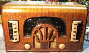
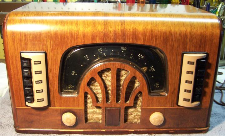
The Zenith 6R631 (Chassis 6B02) from 1942 is a 6-tube AC Superhet circuit radio that
receives only the broadcast band. It features a built-in wave magnet
antenna, push-button or automatic tuning, and the Zenith Radiorgan tone
control system with 5 buttons. The radio had been serviced in the past but most
of the original
parts were still in place. I
decided to try to reverse all prior servicing and restore the original chassis appearance if
possible.
The schematic and a parts list for the radio can be found on Nostalgia
Air. Any part number references in the text below reference that
schematic. |
My
antique radio restoration logs
Overview
The radio was purchased on eBay. Externally it appeared to be all
original, complete and in good condition. The knobs and push buttons were slightly warped (typical for this radio). The
back cover was present but had some damage. The radio
features a tuned RF amplifier stage and 3-gang tuning capacitor in manual tuning
mode, so it should
perform well. However, the RF stage plate load is a 15K resistor rather than an actual
transformer primary, which limits the gain of the RF stage. In automatic (push-button tuning) mode, the first detector stage
is untuned. The radio also features a cut down version (5 buttons) of the Zenith
Radiorgan tone control system. The circuit is quite complex, with a high parts
count. The chassis is small, and access to parts is limited and difficult.
Zenith radios of this vintage use rubber covered wiring which by now has deteriorated
and the insulation will fall off if the wiring is disturbed. Both the
automatic tuning unit and tone control panel are permanently connected to the
chassis. Removal of either switch panel requires removing interconnecting
wiring. To make matters worse, the automatic tuning switch has a cardboard
cover, limiting access.
The eBay
seller published a Youtube
video of this radio working. While there was noise as the radio was tuned,
there was reception so obviously there were no major problems likely.
Previous Servicing
I always attempt to avoid purchasing radios that have been
"restored" by collectors or flippers, and am looking for either all
original examples or those which have been "lightly serviced" in the
distant past by radio service shops.
-
One paper-wax capacitor had been replaced: C5 (B+ bypass for
RF amp and converter).
-
The positive lugs of the filter capacitor had been cut off
and two tubular replacement capacitors tacked in under the chassis.
The original filter capacitor can was still in place.
-
All resistors appeared to be original.
-
Only one likely original Zenith tube remained (and it was
weak and not usable). The rest were replacements. The 6X5G and 6K6G tubes had been replaced with GT types.
-
The power cord MAY have been replaced - the plug was
definitely not original. The cord was the correct type and the installation
looked original, but the cord was simply in too good of a condition to be original!
-
There was a piece of electrical tape around the dial pointer
hub, which was pot metal.
-
New rubber cabinet feet had been fitted.
Cleaning
The chassis was very dusty, but not rusty. The dust was blown off with an air compressor.
The power transformer and IF transformers were cleaned using GoJo (white) hand cleaner and 00 steel wool
and old tooth brushes.
Survey
In Zenith schematics, all
resistors and capacitors having the same value have the same part number call
out. So for example, there may be multiple R2's or C5's on the schematic.
Before I start work on the chassis I annotate the schematic so that all parts
have unique identifiers. I usually add an alphabetic suffix, so that the
part numbers are thus R1A, R1B, etc. I then annotate the chassis photo with
these unique part numbers with a red felt-tip pen. I then removed all
non-original capacitors, documenting their locations
and connections. Since the radio actually worked, there were no major
problems suspected.
I normally measure the values of all resistors as part of the
survey process. But in the case of this radio, there are two cases where
loops exist which prevent accurate measurement of all affected resistors unless
the loop is broken. Otherwise all resistors in the loop will measure
lower than true resistance due to the shunting effect of parallel resistors. The
two loop paths are
shown below (I added a suffix "a" or "b" to indicate two
parts with the same value and part number which are unique parts in the radio):
-
R17 to R16B to R16A to R14 to R11 and back to R17. I
broke this loop by disconnecting R14 (2.7K) from the 7C7 pin 4.
-
R17 to R16B to tone switch 7D (Bass) and back to R17.
I broke this loop by ensuring that switch 7D was open.
-
The power transformer was tested, even though the radio
worked. The AC voltage on both sides of the high voltage center tap was
balanced. Power consumption with no load was less than 10 watts, which
indicated that there were no shorted turns. I always perform this test
prior to restoration, even on working radios, since transformer overheating due to shorted turns or
other problems may not be obvious with only brief testing. Many
collectors new to restoration often completely recap a radio, and even
replace resistors and tubes, only to find out they have a bad power
transformer after completion.
-
Only one of the original dogbone type resistor (R13) was out of tolerance.
Most of the remaining resistors were carbon composition types and all but
three were in
tolerance!
-
The volume control and switch were OK.
-
Both dial lamps were burned out.
-
The tuning capacitor was slanted to the right (view front) and the drive
pulley was rubbing against the speaker frame as well as the back of the
dial. The capacitor is only
attached to the chassis with bent-over tabs through eyelets in rubber
grommets, and was being pulled in that direction by the dial cord. I suspect
that this was due to deterioration of the grommets and/or replacement of the
dial cord which was very likely too tight (the spring had been reconnected
so as to shorten it, thus adding tension). The scratching noises during rotation
noted on the Youtube video could be from the
rubbing or dirty plates or from the pulley rubbing against the speaker frame
or back of the dial.
-
The dial pointer hub (pot metal) was falling apart and only
held together with a piece of electrical tape.
-
The 7Q7 tube (original Zenith) and 7R7 were very weak and
would have to be replaced. The 7A7 RF amplifier was slightly
weak. The remaining tubes tested good; however the 6K6G and 6X5G tubes were
GT types.
-
This vintage of Zenith use rubber covered hookup wire which
has deteriorated. The insulation will fall off, exposing bare wire, if
the wire is disturbed in the slightest way. This wiring has to be
replaced.
Restoration Strategy
Since almost all of the original parts were still in place I decided to try
to maintain the
original chassis appearance to the extent possible. All
original capacitors would be rebuilt in their original cases (restuffed),
including the original
filter capacitor (but the terminal board would have to be replaced since the
original terminals had been cut off). Any parts replaced in
servicing would be replaced with original parts if available. Any out of tolerance
resistors would be replaced with the same types if available. When I replace a component, I
always remove the original part completely from a terminal. Other good components connected at the terminal are protected from heat using old medical
clamps (hemostats). Excess solder is then removed using a solder sucker in order to
expose terminal holes for reattachment of the rebuilt or replaced component.
I assume that all paper and electrolytic capacitors are leaky and thus should be
replaced (I always "restuff" the original components if possible). I
do not replace mica capacitors, but may test them in place if possible (usually
this requires disconnecting one end of the capacitor).
Repairs
Tuning Capacitor
 |
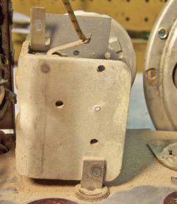
This is what the tuning capacitor looked like as found. It
was tilted to the right and the pulley was rubbing against the speaker frame and
the back of the dial. The tilt was MORE pronounced than shown in
the photo with the dial
cord in place. Removing the capacitor was a complex and
difficult task, involving first removing the dial cord (the stringing is quite
complex) and dial assembly.
I recently restored a Zenith
model 6D2615 which had the same problem.
|
The capacitor was not attached to the chassis with the usual
bolts and nuts. There were three studs welded to the capacitor frame which
ended in tabs which were passed through a flat washer, the chassis hole grommet, and an
eyelet on the other side. These tabs were then simply bent over flat, and
in one case, soldered together.
The capacitor was then reinstalled using new 5/16" (groove
diameter) vinyl grommets. I added an additional flat washer on the two
studs on the right side. When
the dial cord was replaced I made sure that excessive tension was not used for the cord driving
the dial pointer. Excessive tension in this cord likely caused the tuning
capacitor to tilt right as found. The original tension spring had been
shortened, perhaps to overcome the friction problems with the deteriorated pot
metal hub. The dial cord was original. It was found that the pulley still
contacted the back of the dial frame. This was remedied by loosening one
of the screws that secured the dial to the speaker.
Resistors
The radio used two older style "dogbone" type
resistor as well as carbon composition resistors (most of which were 20%
tolerance). One "dogbone"
resistor (R13) was out of tolerance and would be replaced with the same type resistor.
I keep a stock of NOS and used "dogbone" resistors, and buy all I can
on eBay and at radio swap meets (when reasonably priced)! Of course, most of these resistors, even NOS resistors, have also
drifted in value and no longer have their marked values. My solution is to
find a replacement resistor of the correct value and size as measured (ignoring the
markings), and then repaint it to the needed value codes using enamel hobby
paint! In the case of this radio R13 was replaced with a 600K1/4 watt "dogbone" resistor that now measured
643K (-5%).
It was repainted as a 680K resistor using hobby enamel paint (only the end had
to be repainted). Two carbon composition resistors (R2 and R4) were
out of tolerance and were replaced with modern carbon composition resistors (10%
tolerance, since 20% resistors are not available).
The two resistors inside the 2nd IF transformer (47K and 470K)
are not listed separately in the parts list. Both were in tolerance
(20%).
Filter
Capacitor
The filter capacitor was a dual twist lock unit: 15mfd at 350
volts and 20mfd at 250 volts. The original positive lugs had been cut off. It
was very difficult to remove this capacitor from the set for rebuilding since the oscillator coil
is right above it (the coil's mounting lugs are soldered to the chassis!). I can see why the repair person simply cut off the lugs rather than
removing and replacing the original! I found a suitable replacement terminal
board having two lugs in my junk capacitor box. The original capacitor was rebuilt using
15mfd/450volt and 22mfd/250volt radial electrolytics. The crimp around
the base of the unit was uncrimped using an old pair of diagonal cutters.
The ground terminal ring was then removed. The insulator with two positive
terminals was then removed by prying. In this case, the contents were removed
along with the terminal board as a unit. In some cases I have had to clip
the connections between the back of the terminal board and the contents and then
remove the contents separately. In some cases, heat will release the contents
from the can. In other cases I have had to remove the contents using a
spade bit in my drill press and other tools!
The aluminum case was then cleaned. Small holes were drilled in the
replacement terminal board close to the two positive lugs and near one of the ground lugs
(on the metal ring). I use small numbered drills that are only slightly larger
than the lead wire that passes through the terminal board. The two replacement capacitors were then mounted to the
back of the terminal board.
Their positive leads were insulated using small spaghetti tubing
and then passed through the
terminal board and connected to the two positive lugs. A common lead was passed
through the terminal board near a ground lug but not attached until after
the capacitor was re-mounted in the chassis and the mounting lugs twisted. The
terminal board and ground lug ring were then reinstalled (there is a tab on the
ground ring which lines up with a slot in the terminal board). The crimp around
the base was restored using a small tack hammer. I did my best to smooth
things out but the repair is visible.

Paper Capacitors
All except one of the original Zenith branded paper capacitors were rebuilt in their original cases
using modern 630 volt axial film capacitors in order to maintain the original
under-chassis appearance. Zenith tubular capacitors are easy to restuff.
My restuffing process for
these types is documented here. One original Zenith capacitor had been replaced:
C5. This capacitor was replaced using the correct original Zenith dud from my
stocks, which was also restuffed. One capacitor C10 was rated at
0.00075mfd/600 volts. Normally, capacitors in this value range are mica
capacitors. But this one was a conventional paper capacitor. There was
just enough room inside the original case to install two 0.0015mfd/630 axial
film capacitors in series, end to end, yielding the correct value.
Dial Pointer Hub
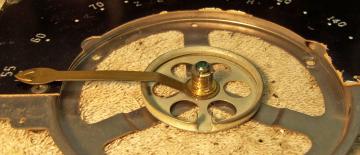
The hub that was fastened to the dial pointer pulley was made of pot metal and was falling apart. As received, it was
held together by a strip of electrical tape. The original construction retained
the dial pointer hand but allowed it to be moved for adjustment purposes. The
stud holding the assembly (attached to the center of the speaker) was 1/4"
in diameter. I used the brass bushing from an old volume control to fabricate a
new hub. The inside diameter was correct and a good fit on the stud. I removed
some of the back of the bushing and turned it down on my small Unimat lathe
until it would fit snugly in the dial pointer hole as well as the pulley. I also
had to remove some of the length to allow for replacement of the C-clip that
retained it on the protruding stud. I used epoxy to attach the bushing to
the dial pulley and the dial pointer, first making sure the slot in the pulley
and the dial pointer were correctly aligned. Since the dial pointer can no
longer be moved or adjusted, it may be quite a challenge to adjust the pointer
position with the dial cord reinstalled! There was an existing felt washer
behind the pulley, but it was slightly too thick and there was too much tension
on the pulley. I replaced the washer (not visible) with a thinner felt
washer from my junk box.

Other Repairs
The GT type tubes were replaced with the correct types: 6K6G
and 6X5G. Other defective tubes were replaced with the same types (loctals
of various brands).
Two rubber covered leads to the second IF transformer had
insulation falling off, risking a short. The transformer had to be removed
in order to replace all of the leads. This was VERY difficult to do. The IF
transformers are secured to the chassis with spring clips, which are then
soldered to the chassis! And there is very little room to work. All the
leads were replaced with similar color cloth covered wire, except that I had to use
black instead of gray (that color is not a standard available color).
The cardboard dust cover around the automatic tuning unit was
falling apart and in several pieces as received. It was repaired by gluing on
strips of file folder material on the inside. In order to remove or reinstall
this cover, three wires need to be temporarily disconnected from the automatic
tuning unit (bottom switch) and attachment screws removed or loosened
temporarily. Fortunately, the connection points are
accessible.
Almost all of the rubber covered wiring that was disturbed had
to be replaced. Fortunately, the most of the wiring to the tone switch
panel was OK. Only one wire needed to be replaced. All of the wiring to
the automatic tuning unit was OK. One filament power lead had to be
replaced.
Cabinet
The cabinet was in good shape. It was cleaned with GoJo hand cleaner
and 00 steel wool. The knobs were cleaned in my old Heathkit
ultrasonic cleaner using dilute ammonia followed by soap, water, and an old toothbrush. No attempt
was made to straighten the warped knobs or push buttons. The
control shafts were squeezed to make future knob removal easier. Removing the
knobs originally was very difficult. The push buttons were cleaned using GoJo
hand cleaner and an old toothbrush and Q-tips. I did not attempt to remove
the buttons from the switch shafts, as that would have likely destroyed the
buttons or the switches.
The dial cover was re-secured to the cabinet using staples. It had shrank
somewhat, leaving a gap in places.
Two ribs on the back cover were broken off. One was found inside the
cabinet. It was reattached to the back.
The two control shafts were
squeezed a small amount across the slot in front in order to make future removal
and replacement of the knobs easier. It was VERY difficult to remove the
knobs originally without damaging them. They were removed by removing the
loop antenna and chassis bolts, then pulling back on the chassis until the knobs
were free. This method allowed the knobs to be removed without prying them off,
which would have risked breaking the knob or damaging the cabinet.
Testing
After the radio was completely reassembled, power was applied through a
wattmeter and fused Variac. Power was brought up slowly while monitoring
the B+ voltage and the wattmeter. The radio came alive and worked, but
only in automatic tuning mode. It did not work in continuous tuning mode.
It was later discovered that one contact on the tuning mode switch (bottom push
button) was bent and no longer making contact with the moving element. Also,
operation of the push buttons was noisy and intermittent, indicating that
cleaning was needed. Access to the contacts for cleaning is very limited by the
construction of the switch panel. During cleaning the contacts with
D5 and operating the switches, the sliding member of the bottom automatic tuning
switch broke in half! It was repaired with epoxy and could then be
operated. Unfortunately one of the sliding contacts originally attached to
the slider was lost and could not
be found. This meant that the bottom automatic button did not work.
The radio was quite sensitive. The tone controls
worked well. However, there was some speaker rattle and distortion or muddiness
on low
bass on certain stations. I have had this same problem on other Zenith
radios. Perhaps there was less bass when these radios were designed? There
was no obvious problem with the speaker cone. It just appeared to be
excessive cone excursion. The solution is to simply depress the BASS tone button
or to reduce the volume when this happens. Some collectors have modified
the tone control circuit to reduce this tendency.
Restoration Results
Most of my restoration objectives were met, but not all. There was no
intention of restoring the set to factory new appearance! My objective is
usually to reverse any prior servicing and make the radio appear to have never
been repaired. I do not go so far as to artificially "age"
solder joints, as do some collectors! Here are some of my
"misses":
- The original radio would have been fitted with all Zenith branded tubes.
- I had to use black instead of gray replacement wire. And the
replacement wire was cloth covered vs. the original rubber covered.
- The bottom automatic tuning button was inoperative, its slider having
broken during cleaning and a contact lost, apparently.
- The back cover (missing part) was not repaired.
- The knobs and push-buttons remained warped.
Chassis Before and After Restoration
Before
|
 |
After
|
 |


