Zenith 6S254 (6-S-254) Console Restoration
 |
The Zenith 6S254 (6-S-254) is a 6-tube console radio with broadcast band and two
short wave bands. The radio had been serviced in the past but most
of the original
parts were still in place. The radio apparently had not been restored (by
a collector). I
decided to try to reverse any prior servicing and restore the original chassis appearance if
possible.
The schematic and a parts list for the radio can be found on Nostalgia
Air. Any part number references in the text below reference that
schematic. |
My
antique radio restoration logs
Overview
My family owned one of this model Zenith console when I was a child. I
fondly remember sitting in front of the radio in our living room listening to the usual old radio
shows of the early 1950's. TV did not exist in our city at the time,
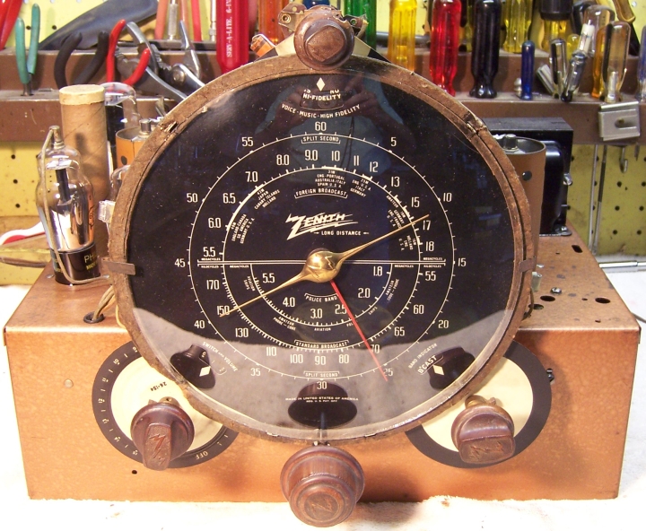
so this radio along with a portable record player provided the kids entertainment. I was always impressed by the big black dial, large tuning
knob with flywheel tuning, copper colored chassis, and the tone.
When TV did arrive in the mid 1950's, the radio wound up in my
"shop" (a reclaimed chicken house) in the back yard. I remember
listening to what is now called "classic country" music for hours at a
time. That radio, like most radios I acquired back then, was eventually
destroyed (sigh) for parts. I have looked for another example for years, but
shipping was usually an issue and pickup from some distant state required (and
no suitable vehicle to transport it). Or else the radio had
already been restored. This radio was found on eBay and only 65 miles
away, so pickup was reasonable. It had not been restored. It was not a particularly good example,
having lots of dings and scratches as well as torn grille cloth (which is
unfortunately no longer reproduced). The seller said that the radio made
"static sounds", so I assumed that most major components were OK.
Previous Servicing
-
The original power cord had been replaced. A rubber grommet
had been installed in the hole in the chassis where the cord goes
through. I am not sure if this grommet is original.
-
The grille cloth was torn and a tear in the speaker cone had been
repaired. Likely the speaker had been damaged when the grille cloth
was torn (penetrated).
-
Two replacement tubular filter capacitors had been clamp
mounted under the chassis. Fortunately, the original filter capacitors were
still in place. The original leads to the filters had been spliced and
could be restored to their original connections to C18 and C19 once these
capacitors were rebuilt.
-
The dial drive belt had been replaced with a piece of dial
cord, which did not work very well (especially since the tuning capacitor
was quite gummed up and very dirty). The tuning knob shaft, drive
pulley, idler pulley assembly, and flywheel had been removed and reinstalled
(incorrectly) for some reason. The front bushing had been
removed and reinstalled backward - with the threaded end inside the
chassis. This prevented the drive pulley and tuning capacitor pulley
from lining up. The rear bushing was also not in place, so that the
rear end of the tuning shaft was just flopping around (the bushing was still
present on the shaft, fortunately). The idler pulley tension spring was attached to the
wrong side, and not attached to the hook designed to hold it. One of the circlips was missing from the tuning shaft, and
had been replaced by a piece of solid wire. I have NO idea why all this was
done. Perhaps the drive belt was slipping or stiff, but intact, and the
shaft was disassembled to remove it or attempt adjustment?
-
Three paper-wax capacitors had been replaced. Two had
been replaced with Zenith parts having the same values but with different Zenith part
numbers. These two may have been replaced by a dealer or Zenith
authorized service shop.
-
R6 had been replaced, its failure likely caused by a shorted
C6 capacitor (which had also been replaced). There were tell-tale blobs of
wax on the chassis mounting board in the general area of C6.
-
One of the dial glass retainer clips had been removed and
the glass secured using Scotch Tape! One dial lamp diffuser had been
repaired using Scotch Tape, and the felt ring cushioning the dial
glass was broken in several places and had been repaired with glue. It's
hard
to imagine why a service person would have gone to the trouble of
disassembling the dial just to repair a diffuser! The dial pan may
have been removed in order to replace the dial drive belt.
-
Three tubes were branded Zenith and two of those had dates codes
containing a "7" (1937?) - the other contained an "11". They may have been
originals. The remainder of the tubes were replacements (Sylvania and
Philco branded).
Cleaning
After removal of the tuning capacitor, tuning shaft and
flywheel, dial assembly and filter
capacitors the chassis and remaining top components were cleaned using an air
compressor followed by GoJo (white) Hand Cleaner and 00 steel wool, and
then toothbrushes and other small brushes. It is critical to keep steel wool far away from a
tuning capacitor or tube sockets.
Survey
These radios are very easy to service because of the large deep
chassis which has lots of space to work. My usual restoration procedure is to make a complete
survey of the condition of all components and repair all items before the radio
is tested. In this case I did briefly test the radio using a variac and
watt meter to make sure the set was really working before providing feedback to
the eBay seller. Minimum power was applied for a short amount of time -
just long enough to determine that the audio worked (touching the top cap of the
6F5G tube) and static could be heard (touching the antenna terminal).
In Zenith schematics, all
resistors and capacitors having the same value have the same part number call
out. So for example, there may be multiple R2's or C4's on the schematic.
Before I start work on the chassis I annotate the schematic so that all parts
have unique identifiers. I usually add an alphabetic suffix, so that the
part numbers are thus R1A, R1B, etc. I then annotate the chassis photo with
these unique part numbers with a red felt-tip pen. I then removed all
non-original capacitors, documenting their locations
and connections. When I replace a component, I
always remove the original part completely from a terminal. Other good components connected at the terminal are protected from heat using old medical
clamps (hemostats). Excess solder is then removed using a solder sucker in order to
expose terminal holes for reattachment of the rebuilt or replaced component.
I assume that all paper and electrolytic capacitors are leaky and thus should be
replaced (I always "restuff" the original components if possible). I
do not replace mica capacitors, but may test them in place if possible (usually
this requires disconnecting one end of the capacitor).
-
The power transformer was OK. The high voltage was balanced
on each side of the winding's center tap with 20 volts applied to the primary through
a variac. It drew less than 10
watts at full line voltage (unloaded), and all filament voltages were correct.
I do this test before starting any restoration. A transformer having
shorted turns usually shows a significant unbalance (more than a volt or
two) across the high voltage and will draw significant power unloaded.
It is very sad to read in the various Antique Radio blogs about collectors
new to the hobby who will completely recap a radio and even invest in
replacement tubes and other parts only to find out after restoration that the power
transformer overheats!
-
The speaker field coil measured open on my DVM, even though
the radio worked!
-
The output transformer measured a high resistance, again,
even though the radio worked (or at least made noise)!
-
The antenna and oscillator coil were OK (tested for resistance and/or
continuity).
-
The IF transformers were OK.
-
Four original dogbone type resistors were out of tolerance
by 30-50%:
R3, R4, R9 (6F5 plate resistor) and R5 (6F5 grid resistor). Five original carbon composition type resistors were also out of tolerance.
-
The wire-wound Candohm resistor R12 was in tolerance and OK.
-
All the supplied tubes were good and were the correct types
(G type).
-
The volume control and switch were OK.
-
The rubber chassis washers and tuning capacitor mounting
grommets had deteriorated and would have to be replaced.
-
One of the dial lamp diffusers had a hole burned in it, and
the other one was broken and had been repaired using Scotch Tape.
-
The felt ring which cushions the dial glass was
broken in several places.
-
Both pilot lamps were burned out.
-
There was a chip out of the top knob (tone control).
-
Dial drive torsion spring was not attached to the tuning
capacitor drive gear. I assume the purpose of this coil spring is to reduce
backlash in the mechanism by keeping the reduction gears in mesh at all times.
-
The dial drive belt had been replaced with a piece of dial
cord and the tuning mechanism was not functional.
Restoration Strategy
Since almost all of the original parts were still in place, and
since this was going to be a "keeper", I decided to try and restore the
original chassis appearance to the extent possible. All
original capacitors would be rebuilt in their original cases (restuffed),
including the original
filter capacitors and the bypass capacitors. Any parts replaced in
servicing would be replaced with original parts if available. Any out of tolerance
resistors would be replaced with the same types if available.
Repairs
Speaker and Output Transformer
Both the speaker field and output transformer (mounted on the
speaker) measured either OPEN or an unstable high resistance - even though the radio
functioned to some extent! I had never seen a failure mode quite like
this. Usually, these components are either OK or not. Discussion
regarding this issue on Antique Radio Forums concluded that the problem was
likely corrosion of the connections between the lead wires and the windings, and
that some significant voltage ("wetting
current") was required to break through this corrosion. The
field coil eventually settled down to the correct resistance. The output
transformer never did. As it turns out, I had a similar replacement
speaker in stock. This replacement speaker was from a Zenith model 7S342
chairside.
It was the same diameter (10") and had the same field coil
resistance. The 7S342 and 6S254 use almost identical circuits and both use
a 6F6 output tube, so the 7S342 output transformer should work in my radio.
However the
speaker from the 1939 Zenith was gold colored (vs. 1938 copper colored) and its cable
was shorter since it was from a chairside set vs. a console. So it
appeared that my choices were:
-
Use the original 6S254 speaker and replace the output
transformer. The issue of course is that the field coil could fail at
any time. Also, it was not known if the repaired cone of the original
speaker sounded OK.
-
Have the original 6S254 speaker field coil rewound (and
possibly reconed).
-
Use the replacement 7S342 speaker and replace or extend the
cable.
Since I did have a repair strategy, I decided to complete the
chassis restoration and test the radio using the original as well as the replacement speaker.
Tuning Capacitor Mounting Grommets
The tuning capacitor was removed from the set, vernier drive
gears removed, and then cleaned using my old Heathkit
ultrasonic cleaner in dilute clear ammonia. The capacitor would not all fit in the cleaner
at once, so several cleanings at different angles were needed. I removed the mica
trimmer insulator before cleaning in order to avoid damage. Before
removal, I noted the position of the trimmer screw (on the clock) and the number
of 1/2 turns to fully tight. By doing this I could return the trimmer to
close to its original position after reassembly. After drying with a heat gun, the bearings
were lubricated using automotive distributor cam lubricant.
The capacitor mounting grommets were replaced using GPH-46-480 grommets from Renovated
Radios. They are not exactly correct, being just a hair too tall, but
seemed to work OK. I probably should have removed about 1/32" from
the thick side.
Resistors
The radio uses both older style "dogbone" type
resistors as well as carbon composition resistors. Any "dogbone"
resistors would be replaced with the same type resistor.
I keep a stock of NOS and used "dogbone" resistors, and buy all I can
on eBay and at radio swap meets (when reasonably priced)! Of course, most of these resistors, even NOS resistors, have also
drifted in value and no longer have their marked values. My solution is to
find a replacement resistor of the correct value and size as measured (ignoring the
markings), and then repaint it to the needed value codes using enamel hobby
paint! In the case of this radio, four "dogbone" resistors had to be
replaced: R3 (10K 20% 1 watt), R4 (33K 10% 1 watt), R5 (1 meg 20% 1/4 watt) and R9 (220K 20% 1/4 watt). For
R3 I found a NOS 15K 1 watt dogbone resistor in
my stock that measured exactly 10K. Thus I only had to repaint the end
color black. For the 33K I used a 20K 1 watt dogbone that was close
enough (+11%) to 33K and repainted it. The original was solid orange with a
silver dot. I repainted the 20K replacement the same way, even though the
usual method of marking would be that one END of the resistor would be silver.
For R9 (the 6F5 plate resistor) I found a 200K 1/4 watt that was close to
220K. It was repainted as a 220K. For R5 I found a NOS 1 meg 1/4
watt dogbone that measured almost exactly 1 meg..
Five 1/2 watt
carbon composition resistors also needed replacement. All of the originals
except R7 (390K) were 20% tolerance - R7 was 10%. I did find ONE 20% carbon composition resistor in my
stock that was in tolerance. But the remainder were replaced by 10%
tolerance resistors (20% carbon composition resistors are no longer available).
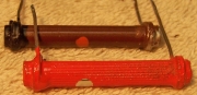
Filter Capacitors
The two original can
type filter capacitors C18 and C19 (both wet type) were rebuilt in their original cases
using new electrolytics. C18, a 16mfd 400 volt capacitor, was restuffed
with a 15mfd/450 volt electrolytic. C19, a 20mfd 300 volt
capacitor was restuffed with a 22mfd/450 volt electrolytic. My restuffing
process for the capacitors is as follows:
- The capacitor is mounted in my small Unimat lathe and the case is deeply scored
about
0.75"
above the screw base. The capacitor is held in the 3-jaw lathe chuck using
the two available original nuts back to back, since the terminal lugs and
screw base will not pass through the center of the lathe chuck (and I did
not want to damage the threads by gripping the capacitor by the threads). The opposite end is supported
the lathe's live
center. I finish the cut with a fine tooth hobby razor
saw - especially if the capacitor still has liquid electrolyte inside (these
were both dry)! I then clean up the cut (burrs) using an Exacto knife with a
sharp #11 blade.
- The center electrode foil is removed, but the center stud is
retained. A solder lug is attached to the center stud
using a 4-40 brass screw and nut.
- The plus lead of the replacement capacitor is attached to the solder lug.
- The negative lead of the replacement capacitor is extended using #22 solid bus
wire and insulating spaghetti tubing routed through a drilled hole in the base of
the capacitor near the outside edge.
- The two halves of the capacitor's case are then reattached using the plastic center of
an empty hookup wire spool - it was about the right size. I often am able to
use PVC plumbing couplings for this purpose, but in this case the smallest
available (1/2" pipe) was too large. If the cut in the
aluminum case is done cleanly, the cut is hardly
visible after reassembly. I normally add a few layers of masking tape
around the plastic coupling to take up any excess space. In this case,
both capacitors have slip-on cardboard covers which would completely hide
the repairs.
- Once the epoxy has hardened, the original top shouldered fiber insulator
is reinstalled. The negative lead of the replacement filter
capacitor is routed through the center of both insulators and then attached to the grounding
lug after the capacitor is mounted on the chassis..
 |
|
Rebuilt Filter Capacitor Cans |
Paper Capacitors
All paper capacitors were rebuilt in their original cases
using modern 630 volt film capacitors in order to maintain the original
under-chassis appearance. The tubular types are easy to restuff.
My restuffing process for
these types is documented here. The two Zenith capacitors (all labeled C6)
that had been replaced with Zenith parts having the same values but different
part numbers were replaced with Zenith parts having the correct Zenith part numbers. Why? Because I had the correct parts in stock! These capacitors were restuffed using new axial film
capacitors (and one of my objectives was to reverse previous servicing).
Mica Capacitors
Any mica capacitors were tested if one end was disconnected in order to replace
another component. C11 (6F5 plate bypass) was rated at 500pf at 600
volts. But it measured only 250pf! It was replaced with a good
identical part from my 7S342 parts chassis. All other mica capacitors that
I measured were OK.
Tuning Mechanism Vernier Drive
The end of the coiled tension spring was bent into a hook shape and attached
to the existing hole in the tuner drive gear. I am guessing that the
original end of the spring broke off in the past. My first attempt also
resulted in the end breaking off, so the spring wound up shorter than the
original. The tuner still seemed to work
OK, and would return on its own after manually moving it to the minimum
capacitor condition.
Power Cord
The power cord was replaced using a new brown vinyl cord with molded
plug (polarized).
Other Repairs
The chassis mounting washers were replaced using CW1 thick
chassis washers
from Renovated Radios.
I was able to acquire a replacement dial glass retainer clip and
screw by posting a wanted advertisement on the Antique
Radios Forum Classifieds. It worked OK, but was smaller than the
original (perhaps for a smaller diameter dial glass).
I found a large O-ring in my stock that was exactly the right
size to replace the dial drive belt. It was found in a bag of large O-rings
purchased at Lowes in the department that sells whole-house water filter
cartridges.
I found a suitable replacement dial drive circlip in my parts
stocks. These and similar parts were salvaged from junk mechanical assemblies
such as record turntables and VCRs.
The dial lamp diffusers were repaired using pieces of an old ice
cream carton, which was similar in thickness and color to the original parts.
The original parts were used as templates and replacements cut out using an
Exacto knife with a new #11 blade. The replacements were attached to the
originals using GC Service Cement.
The dial glass felt gasket was broken in four places. It was
repaired by gluing it to reinforcing material from file folder stock.
Strips of material were positioned on the metal dial pan by cutting slots that matched
the tabs on the dial pan. Waxed paper was used under the strips of
material to prevent them sticking to the dial pan. The broken felt pieces were
then glued to the reinforcing strips using the dial pan for alignment of the
parts. I used GC Service Cement. Once the glue was dried, any excess
material was trimmed flush with the felt ring, and the repair is hardly
noticeable. This method produces a much stronger repair than simply gluing the
broken butt ends of the felt together.
The 6K7 grid lead (exiting from the first IF transformer) was
replaced. The original was very stiff and had a break that was shorting to the transformer
shield. The shield had to be removed in order to replace the wire. I
sometimes effect this repair by removing the grid cap and installing a piece of
spaghetti tubing or heat shrink tubing over the lead.
Both pilot lamps were replaced, but I had only ONE #44 in stock,
so I used a #47 for the other lamp.
Cabinet
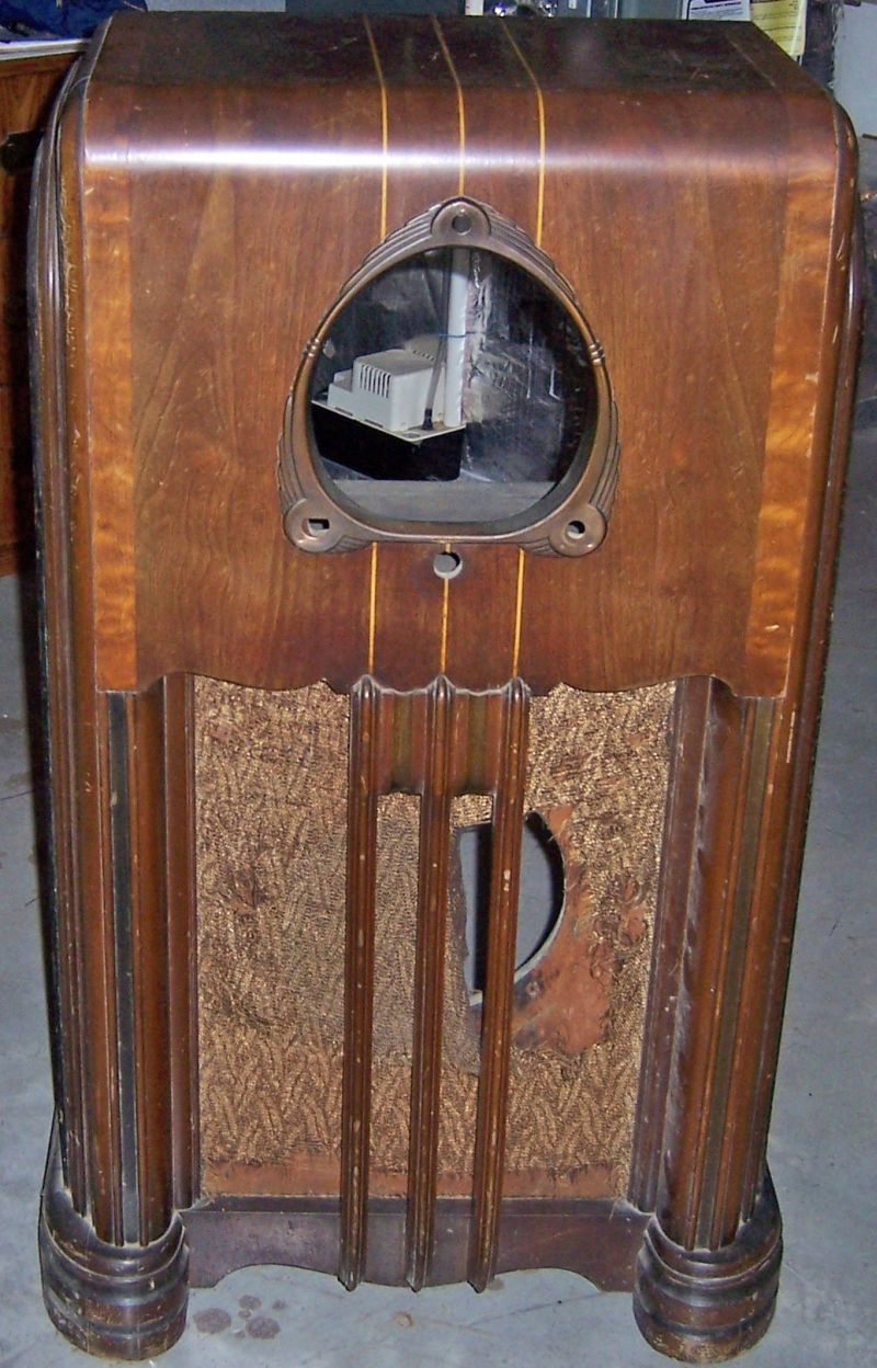
The cabinet was in good shape but had lots of dings and scratches. It was cleaned with GoJo hand cleaner
and 00 steel wool, followed by Old English Scratch Cover (dark) and a coat of Johnson's Paste Wax. The
grille cloth (Zenith leaf pattern) was damaged beyond repair and would have to be
replaced. Unfortunately, the supplier for most of the antique radio
reproduction grille cloth closed up shop, so none is available. Other suppliers
are starting to reproduce cloth, and a small number of examples is
available. This restoration cannot be completed until the leaf pattern
reproduction cloth again becomes available. In the interim, I found a
replacement cloth for a later Zenith console on eBay. It was faded on the
front side, but usable on the back, and was undamaged. This is what is
currently installed.
Testing
After the radio was completely reassembled, power was applied through a
wattmeter and fused Variac. Power was brought up slowly while monitoring
the B+ voltage and the wattmeter. The radio came alive and worked on all
bands - no assembly errors! The radio was then
aligned. The IF transformers were way off. Other adjustments were
close. The volume control was scratchy and was given a couple of shots of GC Big
Bath cleaner. It now works OK, but is not perfect. One of the tuning
capacitor plates was rubbing at the low end of the dial. The offending plate
(antenna section, outside) was bent slightly to fix the problem. This was
done before alignment.
The wave trap adjustment did nothing, even though the coil was good. I
left it as it was since this function is no longer needed.
The original speaker, with its intermittent resistance measurements and
repaired cone, worked perfectly and sounded great.
Restoration Results
Most of my restoration objectives were met, but not all. There was no
intention of restoring the set to factory new appearance! My objective is
usually to reverse any prior servicing and make the radio appear to have never
been repaired. I do not go so far as to artificially "age"
solder joints, as do some collectors! Nothing gives away a restoration
faster than bright and shiny solder joints. Here are some of my
"misses":
- Some of the replacement carbon composition resistors used were 10% vs. the
original 20% types.
- The dial drive belt was replaced by an O-ring. Original flat fabric
drive belts are sometimes found, but have deteriorated just like the
originals.
- As found, only the output filter capacitor C19 had a cardboard
cover. The input filter C18 was darker and showed signs of wear or
corrosion, and thus likely did not have a cover. These covers are
normally used if there is significant voltage on the exposed bare filter
capacitor case. But in this case, there was at most 20 volts on the
input capacitor and 2.5 volts on the output capacitor (the one found with
the cardboard cover). I had a spare cover in my stock, so I installed covers
on both capacitors. It is NOT known if this is correct. These
covers are NOT firmly attached and easily removed and lost.
- The wave trap was not functional and was not restored.
- The replacement line cord differed somewhat from an original, and it is
not known if the chassis grommet is original or a replacement.
- All original wiring was OK as is except the 6K7 grid cap lead, which was
replaced using green stranded cloth covered wire.
- Some components of the dial drive shaft assembly were not original,
including the outside circlip and washer. The exact position of all the
parts was really not known, since this assembly had been removed and
reinstalled incorrectly.
- The correct reproduction grille cloth was not available, so a similar
Zenith used cloth was installed.
- The chipped tone control knob was left in place.
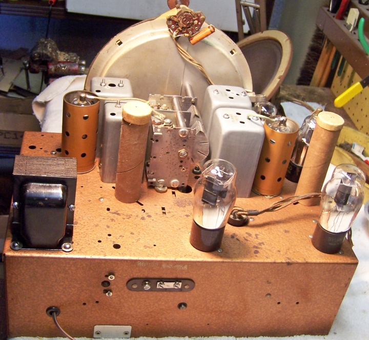
Chassis Before Restoration
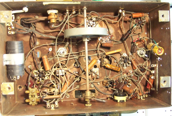
Chassis After Restoration