Zenith Model 8S661 (8-S-661) Console Restoration
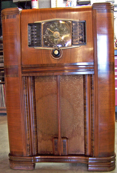 |
This circa 1942 Zenith console radio was found in an antique shop at a
reasonable price, which is rare! The finish was original and in
excellent shape. This is the condition after only cleaning with GoJo
and 00 steel wool. The grille cloth is original and not torn, but
has considerable staining (it was left AS IS).
The
circuit is an 8-tube superheterodyne that receives the
broadcast band and two short wave bands. It has a tuned RF stage for
broadcast band only. It uses mostly G type octal tubes with only one
loctal. It has flywheel tuning and features the Zenith Radiorgan tone
control panel and push-button tuning. The large solid cabinet,
push-pull 6F6G output tubes and 12" speaker deliver excellent tone!
The radio had seen some servicing in the past but had not been hacked excessively.
This being the case, I
decided to try and retain the original top and bottom chassis appearance if
possible.
The schematic and parts list for the radio can be found on Nostalgia
Air. I also ordered a "Service Manual" from A
G Tannenbaum but it turned out to be only a copy of Riders
information. |
My
antique radio restoration logs
Survey
My usual restoration procedure is to first make a complete
survey of the condition of all components in the radio, then replace any
defective parts before any testing is done. To me this is simpler
than diagnosing problems piecemeal and replacement of parts. The survey results guide my
restoration strategy. If major and unique components are defective and
cannot be restored or replaced, I may elect to sell the radio rather than restore it.
I assume that all paper and electrolytic capacitors are leaky and thus should be
replaced (I always "restuff" the original components if possible).
And most original resistors would have drifted and be out of tolerance range.
-
The 5Y4G rectifier tube socket had been rewired to accept a
5Y3 or 5V4 tube. A 5V4G was installed.
-
All other tubes except the 6A8G (which was weak) were
original, or at least branded Zenith. The 6F6G output tubes were weak.
-
The dial drive belt was stiff and would not operate the
tuning control. The seller had ordered a replacement belt from Adams
Manufacturing which was with the radio, and was used in the restoration.
-
The glass dial cover was missing.
-
The station selector buttons were warped, as if exposed to
excessive heat.
-
The volume control knobs was also warped, and the metal
decorative insert was missing. Fortunately, the steering wheel type
bandswitch knobs and tuning knob were present.
-
The power transformer was OK. It drew almost no power
(10 watts or so) unloaded at 120 volts input. All
output voltages were correct,
and the high-voltage winding was balanced on each side of the center tap.
-
The speaker field and output transformer were OK.
-
All RF coils and transformers were OK.
-
The original rubber power cord was usable (the plug was not
original).
-
Much of the rubber wiring, including wiring to pilot lamp
sockets and Radiorgan tone control panel had deteriorated and was crumbling.
If a wire had intact insulation and it was not necessary to move it, I
generally left it alone.
-
The tuning capacitor mounting grommets had deteriorated.
-
All tube shields were in place.
-
Six original Zenith tubular capacitors had been replaced in
previous servicing (the replacements were branded Sprague).
-
Both pilot lamps were burned out.
-
Five resistors were out of tolerance. One (R18, the
6F6 cathode bias resistor) was a replacement, which was open. The
original is listed as a 470 ohm 1.5 watt wirewound. One defective resistor was a
dogbone type, but the rest were standard carbon composition types.
-
The volume control (R10) with its two taps was good
(fortunately) as well as the attached switch. This control would have
been difficult to replace, and its value is critical since it is part of the
complex tone control system.
Cleaning
I normally clean the chassis before starting restoration.
I first blew off the above and below chassis dust with an air compressor.
The chassis was then partially disassembled for access and cleaning. The
tuning capacitor, dial drive mechanism and flywheel assembly was removed after
unsoldering the leads and ground braids. All these parts were cleaned
prior to installation.
The chassis and top components (coil shields) were cleaned using GoJo, steel wool, and
toothbrushes.
Repairs
Before repairs were begun, a photo of the underside of the chassis was made
and printed. All parts (resistors, capacitors, coils, trimmers) were noted
on the photograph (using arrows from notations in the margin). Since the
parts are not unique (i.e. the schematic has several resistors noted as R1 - all
with the same value) all parts were made unique by adding suffixes such as R1a,
R1b, C1a, C1b etc. The schematic was then annotated the same way.
Defective and non-original parts were highlighted on the photo.
All alignment trimmers were also noted on the photo, since I was unable to
find any documentation for this set that indicated where the trimmers
were! The trimmers and broadcast padder were identified by tracing the
schematic.
- All original Zenith wax-paper capacitors were rebuilt in their original
cases using modern 630 volt film capacitors in order to maintain the original
under-chassis appearance.
- All non-original capacitors were removed. The correct Zenith parts
were then located in my dud capacitor stock (I have a good collection of
branded wax-paper capacitors just for this purpose). Zenith capacitors
are all identified with part numbers on the schematic, so the correct parts
could be identified. The correct Zenith parts were then restuffed.
- A replacement plastic dial cover was ordered from West-Tech
Services.
- A reproduction volume control knob was ordered from Alan
Jesperson.
- The replacement dial drive belt from Adams
Manufacturing was installed.
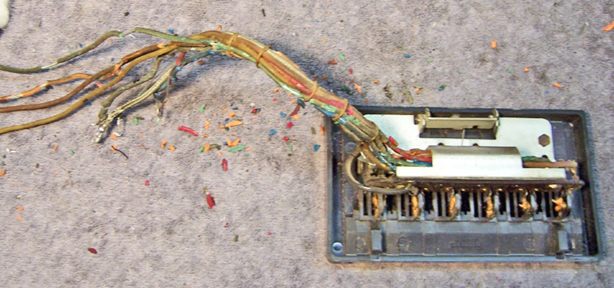
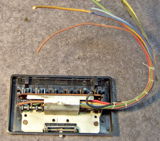
- The rubber wiring to the Radiorgan tone control panel was crumbling and
had to be replaced. The harness was laced like the original.
While disassembled, the contacts were cleaned of old dried grease and
tested.
|
Audio Control Panel Before Restoration |
After Rewiring |
 |
 |
- The main filter capacitor was a 20+20mfd 450 volt FT type twist lock can
capacitor. It was replaced by a NOS 20+20/450 and 20/25 volt FT type
capacitor which was reformed and tested. This capacitor reformed very
quickly and had minimal leakage afterward. It was however about
1" shorter than the original. To hide that fact, I placed a black
cardboard cover over it (I have not decided which looks better - a shorter
than original filter capacitor or the black cover).
- I was able to acquire two good used, tested and closely matched 6F6G
output tubes at the Charlotte, NC AWA conference. These were
installed, along with a NOS 6A8G and 5Y4G.
- For R18 (the 6F6 cathode bias resistor) I installed a large 3 watt dogbone
resistor which was repainted for 470 ohms using hobby paint (it was
originally a 500 ohm unit, measured 503 ohms). Since the original R18
had been replaced, I had no clue as to what it looked like (probably a
flexible wire wound unit). R15 (220K 1/4 watt dogbone) was replaced
with another repainted dogbone resistor that measured within 10% of
220K. The remainder of the defective resistors were standard 1/2 watt
carbon composition types.
- I replaced the tuning capacitor mounting grommets with standard rubber
grommets. That worked OK, although they are really too stiff.
- C21, the line to ground capacitor (0.005uf at 600 volts) was a Micamold
type, and it was of course leaky - not good! I sliced it open using a
Dremel tool and cut-off disc, hollowed out the inside with milling tools,
and inserted a 0.0047uf/630 volt film capacitor. The two halves were
then reattached using epoxy. The resulting repair/restuff is not
obvious.
- The old, stiff grease on the station selector unit switches was removed
using lacquer thinner and Q-Tips.
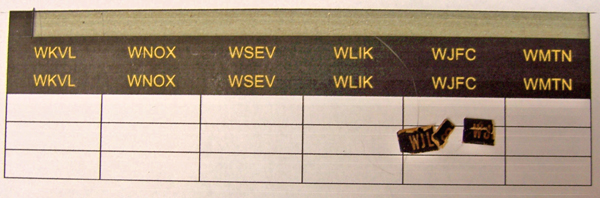
Push Button Station Selector Panel
The push buttons on the original station selector panel were warped and
distorted. Perhaps they were exposed to heat. The panel itself was
not damaged. I obtained a replacement tone control panel on eBay that had
the correct buttons which were in good shape. I originally planned on
replacing the individual buttons from the donor unit. I then noticed that
the station selector panel was the same as the tone control panel, except turned
upside down! So I was able to simply cut the metal bracket that held the
tone control switches with a Dremel tool and also slice off the plastic switch
tabs from the back of the buttons. But this left the tone control labels
on the switches visible (and upside down). There were remnants of existing
stations labels installed. I was able to use these as a pattern and fabricated some stations
selector labels from paper, cut them out, and inserted them into the push
buttons. The station adjustments were later tuned to the indicated local
stations.
Testing
After the radio was completely reassembled, power was applied through a
wattmeter and fused Variac. Power was brought up slowly while monitoring
the B+ voltage. The radio worked the first time. The radio was then
aligned. Since several resistors in the phase inverter circuit had been
replaced, I then wanted to make sure the output tubes were close to balanced
(the 6F6G tubes were measured at 1980/2000 and 2000/2000). I applied an
audio tone from my signal generator to the volume control and measured the
voltage on the plates of the 6F6 output tubes. Initially, the voltage was
about 10% different. I then played around with the 6F6 grid resistor using
a resistance substitution box until the voltage was about equal on both
plates. I then installed a suitable resistor. It turned out that the
needed value was 346K (the schematic called for 330K 10%). The existing
resistor had drifted to about 369K. I found a suitable dogbone resistor
and repainted it as 330K using hobby paint.
The radio has great tone and is very sensitive.
|
Chassis before restoration |
Chassis after restoration (C21 not yet installed) |
 |
 |
|
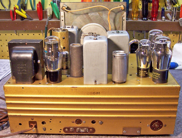
Chassis Top Before Restoration |
 |
|
Chassis Rear After Restoration |
 |
|
Rear View of Cabinet |
 |