ERLA 271-A Restoration

|
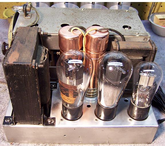
The Erla 271-A Tombstone, circa 1931 is a 7-tube TRF circuit
radio, made
by Electrical Research Labs, Chicago. The unique feature of this
radio is an electric clock mounted in the center of the speaker.
The radio had seen some servicing in the past, but most of the original parts were still in place. I decided to try
to maintain the original above and below chassis appearance and to reverse
all previous repairs to the extent
possible. The schematic for this radio can be found on-line at Nostalgia
Air. |
My
antique radio restoration logs
Condition As Found
This radio was purchased on eBay. The cabinet was in
good original condition, as were the
knobs and grille cloth - just the usual wear, dings and scratches. The
radio was sold as working, but with the clock not working. There was no evidence that the radio had been
restored by a collector - only normal radio shop servicing long in the past. Even the line cord was original, but in
poor shape. I always avoid knowingly purchasing a radio that has been
restored by a collector, as many take shortcuts such as removing the original capacitors and filters.
There
was unfortunately some damage in shipment. The radio had been packed in
the typical Chinese shipping carton. These are not very sturdy. The
only padding was a 1" layer of Styrofoam all around, and this is a VERY
heavy radio. During shipment the speaker baffle board had separated from the
cabinet, allowing the speaker with baffle attached and the clock to rattle
around in the cabinet! Fortunately, the clock did not appear to have been
damaged. But there was damage to the fragile speaker cone, and cosmetic
damage to the output transformer (it still worked, although one secondary lead
was broken and insulation scuffed, exposing some of the secondary winding). The baffle to cabinet attachment was simply a few small
screws. It is very likely that this damage would have occurred
regardless of how well the radio was packed, unless the speaker had been removed
for shipment.
When tested, the radio actually did work as stated, so all major
parts should be OK.
Previous Repairs
-
All the tubes had been replaced, probably more than
once! All tubes were
shouldered or ST type. The radio originally would have been fitted
with globe type tubes (the sockets were marked 245, 280, 227 etc.)
-
One paper capacitor had been replaced (the original would
likely have been a Dubilier CUB type, one of which was still in
place). Most of the bypass capacitors were in metal cans and original.
-
The filter capacitors had been replaced - the originals were
Merchon copper screw-based units with the plus terminal at the top rather
than under the chassis. The original female mogul screw bases were still
present.
-
All the original resistors were still in place.
-
The dual tandem volume control with switch had been replaced
by a single control, which was now bad.
-
The AC plug had likely been replaced.
-
One RF amplifier tube grid cap had been replaced by a bent
piece of metal.
-
There were some taped repairs to the AC cord inside the
clock, which had likely shorted out sometime in the past (where the cord
passes through a hole in the metal back of the clock, which has no grommet).
Survey
My usual restoration procedure is to first make a complete
survey of the condition of all components. The survey results guide my
restoration strategy. If major and unique components are defective or
missing and
cannot be restored or replaced, I may elect to sell the radio rather than restore it.
I always assume that all paper and electrolytic capacitors are leaky and thus should be
replaced (I always "restuff" the original containers if possible).
Any mica capacitors are assumed OK until testing proves otherwise. Since
the radio actually worked, no major components were defective (RF coils, chokes,
transformers, RFCs,
etc.)
-
The line voltage selector toggle switch on the back was bad (it measured a high resistance) - dirty and/or oxidized contacts
were likely.
-
The volume control (not original) was open.
-
One chassis bolt was missing.
-
Most screws holding the speaker baffle board were missing.
-
The speaker field was OK.
-
The speaker cone was torn in several places due to shipping damage.
-
The output transformer was OK (some cosmetic damage in shipping).
-
The audio input transformer was OK.
-
The filter choke was OK (fortunately - it has a very unique construction)
-
The power transformer was OK.
-
All tubes were good, although globe types would be correct for this
radio.
-
The power cord was original (black twisted cloth covered) but in poor
condition. The plug had been replaced.
-
Two original dogbone resistors were out of tolerance. The 45 tube filament
shunt resistor was broken.
-
Almost all wiring in the radio was cloth covered and was OK.
-
The clock was stated as not working. When started, it would actually
run for a few seconds. I suspected that it simply needed cleaning and
lubrication.
-
Whatever retained the pilot lamp socket was now missing.
Repairs
At this point I made BEFORE photos of the chassis bottom. I use these photos to ensure that replacement parts and
wiring are placed as close as possible to their original positions. Some
radios are subject to problems (such as oscillation) if wiring is re-routed or
lead dress is not the same as the original..
All tubes and tube shields were removed. The tuning capacitor and dial
assembly was removed for cleaning and access to other parts on
top. All non-original parts were then removed.
The top and sides of the chassis was cleaned with GoJo hand cleaner and 00 steel
wool. Since this process may leave small steel wool fragments that can cause
problems later, I follow up with a thorough vacuuming and go over everything
with a small magnet and masking tape to pick up any stray fragments.
The power cord was replaced with old-style black twisted lamp cord available
from Grand Brass Lamp. It is not a
real close match to the original, but is all I could find! It is at least
black and twisted, but is somewhat thinner than the original. The covering
is synthetic material, vs. cotton on the original. The cord set came with
an old style molded plug, which was retained (the plug that came with the radio
was not original). The socket for the clock was re-used.
A new #41 pilot lamp bulb was fitted. A rubber grommet was used to
mount the lamp socket onto its bracket.
Volume Control
The volume control on this radio originally was a ganged wire wound control
with switch One section was 5K ohms and controlled the screen grid
voltage of the three 224 RF amplifier tubes, and thus the gain. The other
section was 10K ohms and was an antenna shunt. I contacted Mark Oppat
about a replacement part. He said that they were not available (he can
normally supply almost any vintage replacement potentiometer). There was a
work around available but the radio would have to be modified and rewired to use
a single control. I wanted to avoid that if possible.
The original control had been
replaced by a single 10K ohm wire wound control with attached switch, controlling
only the screen grid voltage to all three RF amplifier tubes. This replacement was now defective. There
was no continuity between the low end of the wire wound element and the rheostat
terminal, thus providing only limited control of volume. This control was repaired by:
- Inserting a paper thin sliver of brass about 1/8"x3/8" (material
normally
used for model railroad construction) between the
resistance wire and the outer insulation on the low end of the control. The brass was
first sanded until bright, and then cleaned.
- Drilling a small hole adjacent to the low end terminal through the insulation.
- Attaching a thin wire to the terminal, threading it through the drilled hole, and
soldering it to the top of the brass insert (now in contact with the low end
of the resistance wire)
The repair was successful - the control measured 10K ohms and the resistance
varied smoothly as the control was rotated.
Clock
The Hammond clock used in this radio is not self-starting. One must
push in on a rear knob and spin counterclockwise to start it, and the speed of
the spin is critical! If power fails, the clock must be restarted!
But one must first remove the clock from the radio in order to restart it or set
it - the controls on the back are not accessible from the rear. There is a rotating indicator disc on the front of the dial, which indicates
that the clock is running. The clock was sold as not working. I had hoped
that the seller and other eBay bidders simply did not know that the clock must be manually
started! When tested, the magnet coil was OK. The clock would runs
for a few seconds after starting and then quit. I suspected that the
mechanism needed cleaning and lubrication. In some cases the motor capsule
must be rebuilt - a task for an experienced clock repair shop, since the
bushings inside the capsule are likely worn and have to be replaced.!
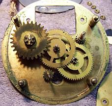
The clock was completely disassembled, and all parts cleaned in lacquer
thinner. To keep track of all the various parts, I took photos as the
mechanism was disassembled, kept the parts in order through the cleaning
process, and made careful notes. Below are the first few steps of the
movement disassembly.
There did not appear to be any pivot holes with excess wear that would
prevent the gear train from working correctly - lucky! If heavily worn,
and the pivot holes oblong in shape or much larger than the pivots, the gears may jam.
The
movement was very dirty and caked with hardened and oxidized grease or oil. The pivot holes in the plates were cleaned with wooden toothpicks and/or
pipe cleaner soaked in lacquer thinner. The movement was then reassembled
and the pivots lubricated with proper synthetic clock oil. The wiring
inside the clock case was taped and a splice found that was not even soldered! This was
repaired using shrink tubing and electrical tape, thus retaining the original clock
cord and plug. Once assembled, the clock started and continued to run and
to keep time. I did not mess with the motor capsule - just some lubrication
on the front shaft and bushing.
Resistors and Capacitors
The 45 tube filament shunt resistor (20 ohms, center tapped) had broken near
the tap terminal. I was not able to repair it. It was replaced by a
50 ohm wire wound resistor of similar size and appearance - but this replacement
resistor did not have a center tap.
I was able to remove the tap terminal from the original resistor and attach it to the
replacement. I did not manage to get the tap attached to the exact center
of the replacement - the two halves measured 15 and 17 ohms. Hopefully the hum
will not be excessive due to this imbalance. Two dogbone type resistors
were out of tolerance, but thankfully most others were very close to correct. One
large 10K ohm 2 watt dogbone resistor was replaced by a similar type resistor which was
slightly larger. The replacement was originally a different (lower) value but had
drifted to the correct value over time! It was repainted to match the
original resistor using hobby paint. The 45 output tube cathode (filament)
bias resistor (1500 ohms) was about 30% high and I did not have a suitable
replacement in stock. So I cheated! A shunt resistor was hidden
inside the restuffed cathode bypass capacitor (1mfd) so that the resistor now
measured the correct value.
All of the bypass capacitors in the set were metal cased units with 1 to 3
capacitors inside. The capacitors were removed from the chassis and contents
removed, retaining the original terminal strip and insulation. Only the
capacitors and potting compound were removed, taking care not to damage the
insulation and terminal board. The cases and insulation
were then soaked in paint thinner and cleaned with old toothbrushes. Suitable new film
capacitors were placed inside, connected to the original terminal board, and the
capacitor then filled with melted rosin/wax salvaged from servicing 1924 RCA
Superheterodyne catacombs. This wax melts at a low temperature and will
not damage components. The rosin/wax keeps the replacement capacitors and
the terminal strip in
place. In one case I noticed that the capacitor had one 0.1mfd and two
0.25mfd 200 volt capacitors, but the 0.25mfd units were used in parallel.
This capacitor was restuffed with one 0.47mfd 630 volt capacitor rather than two
0.22mfd units. One original metal cased capacitor had lost its paper
label. I scanned the an existing label and attached it to the capacitor
missing a label.
There were also two tubular capacitors used. One was the second detector
plate capacitor (0.004mfd) and the other was the audio coupling capacitor
(.01mfd). The audio coupling capacitor was not original, and had been
replaced by a 500pf paper capacitor! That could not have worked very well
- frequency response would have been limited and gain reduced. The other
capacitor looked to be the original Dubilier CUB type capacitor. I thus
assumed that the audio coupling capacitor should also be a Dubilier CUB type. I
collect branded dud capacitors (Zenith, Philco, RCA/GE, and Dubiler Cub) for the
purpose of "reversing" previous repairs. I had a Dubilier CUB
capacitor in stock, but it was not a 0.01mfd. I restuffed it with a
0.01mfd/630 volt film capacitor, and installed it in the radio so that the value
marking was not visible - only the Cub label. Here is my method of restuffing
Dubilier Cub capacitors, which are quite unique in appearance. The
second detector plate bypass capacitor was original. It was hoped that it
was not leaky and thus could be retained (some low value capacitors test out
OK). But alas, it showed a leakage resistance of only 500K ohms on my Tel-Ohmike
TO-4 capacitor tester, and I did not feel I could trust it. It was
restuffed using a 0.0047mfd/630 volt unit. In this case there was no
cardboard tube - the label was attached directly to the paper/foil roll.
So I slit the label and foil with a razor blade and removed the label. A
found a suitable cardboard tube in my dud capacitor stock, restuffed it,
attached the original label, and then attached the original metal end
caps. The slit in the label was positioned so as not to be visible when
the capacitor was reinstalled.
Mershon Filter Capacitors
The original Mershon screw based filter capacitors had been replaced in prior
servicing. These units are quite unique: they are made of copper and have a large
mogul base that screws into a brass socket riveted to the chassis.

This provides the
negative terminal. The positive terminal is on the TOP of the capacitor,
and there is a copper cap that protects prying fingers from the full B+ voltage
present! Fortunately,
the sockets were still in place. I was fortunate to be able to purchase
two original capacitors from the good folks on AntiqueRadios.com
classifieds. Unfortunately, these did not have the original covers,
since the capacitors had been clamp mounted under the chassis of the donor radio
(the owner elected not to restuff them since they were not visible). But I found that
normal plumbing hardware (1.25" pipe caps) fit well and were at least
similar to the originals. I have seen photos of pipe caps that do look
like the originals - I will keep my eye out for them when visiting Lowe's etc.
or large hardware stores. The capacitors were originally 8mfd. They
were restuffed using 10mfd/450 volt capacitors. To restuff them, the capacitors
were first chucked in my small Unimat lathe and their cases deeply scored about 1" down from
the top (terminal end). A mark was scratched on the case across the
planned cut in order to maintain the original orientation and thus a snug fit. The
cut was then completed using a hobby razor
saw and cleaned up using an Exacto knife. This left only a thin line on
the case - hardly visible. The original contents (insulator and liquid
electrolyte) were then removed. The original
positive element inside was removed and the stud was cut short and then drilled and
tapped to accept a ground lug and 8-32 screw. The
capacitor case was then cleaned and polished using Brasso. The positive
lead of the replacement 10mfd/450 volt capacitor was attached to the ground lug.

The negative lead of the
replacement capacitor was extended and soldered to the inside lower part of the
case, since this part mates with the screw base on the chassis and provides the
negative connection.

The two halves
of the copper case were then rejoined using a piece of a 1" PVC plumbing
coupling wrapped in
masking tape (to ensure a snug fit inside the case) and attached to both halves of the case using epoxy.

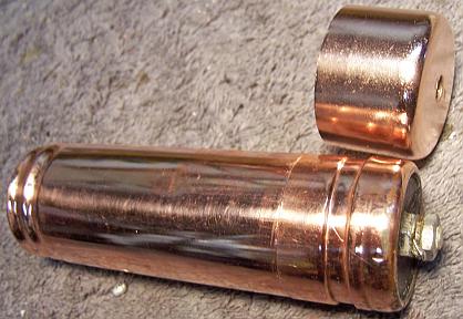 |
 |
| Finished capacitor with a 1.25" pipe cap to replace the missing top cover. |
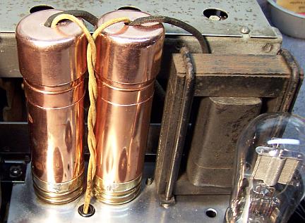
Finished capacitors in place in the radio.
I later found out that the originals had rubber grommets installed! |
Tubes
The radio was re-fitted with globe type tubes for the 280, 245, and 227
driver tube - these tubes are visible. The remainder of the tubes are
inside shields, and not visible. The original tubes were left in place,
since they were good.
Cabinet
The cabinet only needed a good vacuuming inside and then cleaning on the
outside with GoJo and 00 steel wool. The speaker baffle board was
reattached securely with additional screws (holes were extant). The top of
the cabinet was loose from one side - the glue joint had failed, perhaps due to
shipping. The crack was glued and clamped.
Testing and Alignment
Once the radio chassis was reassembled and the tubes installed, power was brought up
slowly using a variac. AC power consumption was monitored using a watt meter, and a
DVM monitored the B+. The radio powered up and worked immediately. The radio was then
aligned. The radio performs well, is quite sensitive and has very good tone. The
rebuilt volume controls works smoothly. There is minimal hum, so that the
45 tube filament shunt resistor center tap was close enough! The
patched up speaker cone seems to work OK - no rattles and reasonable tone
quality.
Restoration Results
Chassis Bottom Before and After Restoration