General Electric Model L-50 Restoration
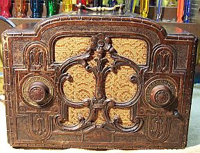 |
The GE Model L-50 with repwood cabinet (which uses the same chassis as the RCA model R-22) is a
5-tube AC (or DC) Superhet
circuit radio that
receives the broadcast band and one short wave band. The radio had been serviced in the past,
but most
of the original
parts were still in place. I
decided to try to reverse all prior servicing and to restore the original chassis appearance if
possible.
The schematic and a parts list for the GE L-50 can be found on-line on Nostalgia
Air.
|
My
antique radio restoration logs
Overview
The radio was purchased at the 2014 CC-AWA Convention and swap meet
in Charlotte, NC, and was sold as not working. The circuit it uses is quite unusual
for several reasons:
-
The radio operates on either AC or DC, but a switch on the
back selects which type of power! In AC mode it uses a voltage doubler
circuit, and the performance should be significantly better than in DC mode. The
power supply, while quite simple, is also quite clever. In DC mode, it
blocks power to the filter caps and radio if the plug is reversed. It
should also even work on AC power in DC mode, but at a reduced level of
performance, since only half-wave rectification is used.
-
It has a tuned RF amplifier stage, but no IF amplifier
stage. It compensates for this by using an type 77 anode bend
detector stage rather than a simple diode second detector. This type
of detector provides the audio gain needed without having to have an audio
amplifier stage. But distortion is higher, and there is no Automatic Volume
Control (AVC) function provided.
-
It receives the broadcast band and a "police" or
short wave band of only 2.4-2.5mHz. For this band, the RF amplifier
and first detector stages are untuned and essentially broadband. Thus
there would be severe problems with images.
-
The band switch is a small wooden dowel protruding from the
front of the cabinet near the tuning knob. There is no knob - just the
protruding dowel. Almost every GE L-50 I have seen is missing this part,
since it is very fragile. The dowel must be turned 90 degrees to switch
bands. If turned too far the dowel can be damaged and the radio would no
longer work correctly. I was excited to find a radio with this part and its
associated mechanism still intact. Most recent eBay and Radio Attic
sales of this model, as well as some photos at Radio Museum, are missing this part. If
removed completely from the radio, the radio will work correctly on the
broadcast band. The "sort of" short wave band is useless
anyway.
-
I had previously purchased another example of this radio on eBay, but
it was destroyed in shipping due to terrible packing! It was not
restorable, and an insurance claim was filed. That radio was also
missing the band switch shaft and mechanism. But it did have the
original filter capacitors in place. Unfortunately, the Post Office
wanted it brought in for scrapping! I would have loved to have the
chassis for a parts set!
Servicing this radio is very difficult due to the compact chassis, high
parts count, and relatively large components used in RCA/GE radios of this
vintage. The radio appeared to have been built in layers, and some parts have to
be removed in order to gain access for servicing. All the resistors used were old-style "dog bone"
types. A large wire wound resistor was also used which functioned as the
filament dropping resistor. Adding to the complexity, the original filter
capacitors had been replaced by a twist lock type capacitor mounted on ceramic
stand-offs on top of the chassis. The filter protruded from the back of
the radio and would be "hot" to AC even if the radio was switched off.
The RCA/GE parts placement
diagram provided in Riders did not match my chassis. What were originally
individual paper capacitors had been replaced by two RCA/GE capacitors containing
multiple units - likely an undocumented production change to simplify assembly.
One such capacitor contained two capacitors (C1 and C25) and had three
leads. Another contained three capacitors (C12, C13 and C27) and had four
leads. Part C24 was not found, and likely eliminated in a production change or when
the filters had been replaced. The
IF transformer and second detector plate choke are very fragile with exposed,
unprotected wire leads which are easily damaged.
Previous Servicing
I always attempt to avoid purchasing radios that have been
"restored" by collectors or flippers, and am looking for either all
original examples or those which have been "lightly serviced" in the
distant past by radio service shops, rather than peppered with new film
capacitors. This radio had received prior
servicing, but most of the original
parts were still in place. It was not clear who might have done this repair
- it appeared too extensive and complex for a service shop repair.
- The band switch shaft notches had been enlarged and modified. A
C-clip had been added to the outside end.
- The two cardboard cased filter capacitors had been replaced. A four
section twist lock capacitor had been mounted on the chassis on ceramic
stand-off spacers (the chassis is NOT at B- potential). Two additional
tubular electrolytics had been mounted under the chassis. The
replacement capacitor had not been wired per the schematic, and its
capacitance was much larger than the original capacitors. I have
seen other examples of this radio with non-original but similar/compatible
cardboard case replacement filter capacitors. So replacements must
have been available early in the life of this model.
- The AC/DC toggle switch had been removed.
- All of the original dogbone resistors were still in place.
- All of the original paper capacitors were still in place, although I never
found part C24. C24 (0.1mfd) originally would have essentially bypassed the
output filter capacitor and thus prevent any coupling between stages.
It may have been removed when the filters were replaced, or may have been an
RCA/GE production change.
- The original cloth covered power cord and plug were still in place and
safe to use.
- The original antenna and ground leads had been removed. A new hank
of wire had been added, but only connected to one of the antenna coil
terminals (and thus would not have worked very well).
- Only two of the tubes were branded RCA-Cunningham, so the remainder were
replacements. A 6D6 replaced the type 78 tube.
- The tube shields had been removed - they are very difficult to re-install
in the cramped chassis, so they likely would have been discarded after tube
servicing.
- Some new wiring had been added due to changes needed for filter capacitor
replacement.
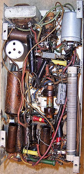
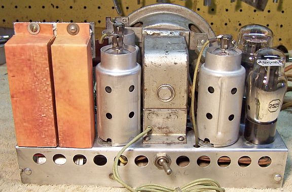
Chassis Before Restoration - Back View - Filter Caps
Replaced
Tube Shields Missing - AC/DC Switch Removed
|
 |
Cleaning
The chassis was very dusty, but not rusty. All tubes and tube
shields were removed. The dust was blown off, top and bottom, using an air
compressor. After removal of the volume control, speaker, and tuning capacitor the top of the
chassis was cleaned using using old tooth brushes and a vacuum to remove dust
from the crevices. Parts of the chassis were then cleaned with GoJo (white) hand
cleaner and 00 steel wool. All of the paper capacitors had been previously
removed before removal of the speaker, since some of its connections otherwise
were not accessible. Since steel wool may leave behind small metal fragment, I
went over the chassis with small magnets just in case. Some of the gunk on
the chassis was very difficult to remove.
The tuning capacitor was partially disassembled for
cleaning. All the trimmer screws, washers, and mica sheets were first
removed, as was the band switching contact assemblies and brass stator grounding
fingers. Prior to removing
the trimmer screws, the current position of the trimmers were documented so they
could be returned to their approximate original positions:
-
The original position of the trimmer screws on the clock was
noted.
-
The screw was then tightened fully, noting the number of 1/2
turns (and fractions) to tight.
-
The screw was then removed along with the washer and mica
insulator.
-
After cleaning, the process was reversed. The mica strip,
washer, and screw were re-installed.
-
The screw was again fully tightened.
-
The screw was then loosened the correct number of 1/2 turns
The tuning capacitor was cleaned in my old Heathkit ultrasonic
cleaner using dilute ammonia. Multiple cleanings in various positions were
needed, since the capacitor would not fit in the tray. After cleaning, I
used soap, water and old toothbrushes to clean up the capacitor. The
capacitor was then towel dried and then dried using a heat gun. The front ball
bearings were lubricated using automotive distributor cam lubricant.
Survey
Before starting
restoration I made photos of the chassis bottom for reference. I then annotated
a copy of the schematic, as well as the chassis photograph, with reference part
numbers (R1, R2, C1, C2, L1 etc.).
-
The band switch shaft was broken, but all its parts were
present.
-
The speaker field coil was OK.
-
The output transformer and speaker cone were OK.
-
The filter choke was OK.
-
All RF coils and the IF transformer were OK.
-
The power switch was originally inoperative. After a
shot or General Cement Big Bath spray cleaner and repeated cycling, it then
worked.
-
The volume control was intermittent and indicated open
circuit at certain points.
-
Two small resistors were out of tolerance by more than 20%
(some as high as 50%). One was a 1/2 watt dogbone, and one was a 1/4
watt dogbone.
-
The wire wound power resistor R9 was OK.
-
The power cord was original and safe to use.
-
One chassis bolt and washer were missing.
-
The 25Z5 tube was dead on one side, likely due to a B+
short. The 6A7 and 77 tubes tested slightly weak. The 43 tested good.
Restoration Strategy
I assume that all paper and electrolytic capacitors are leaky and thus should be
replaced (I always "restuff" the original components if possible). I
do not replace mica capacitors, but may test them in place if possible (usually
this requires disconnecting one lead of the capacitor).
Since almost all of the original parts were still in place I decided to try
to maintain the
original chassis appearance to the extent possible. Normally I would
rebuild all original wax-paper capacitors as well as the filter, block, and can capacitors in
their original cases (restuff them). In this case, the original cardboard
cased filter capacitors had been removed. So I would have to try to
reproduce them (I did have photos of the originals used from my damaged example
and other on-line sources).
When I replace a component, I
always remove the original part completely from a terminal. Other good components connected at the terminal are protected from heat using old medical
clamps (hemostats). Excess solder is then removed using a solder sucker in order to
expose terminal holes for reattachment of the rebuilt or replaced component.
The RCA/GE terminals used in this vintage radio are quite
fragile and must be handled with care. Most consist of three legs with a gap
between the two outer and center leg. When assembled, the various wire
leads and components are placed in the gap and then the three legs are crimped
closed and soldered. In order to service any wires or components, I first remove
as much solder as possible using a pump-type solder sucker. I then VERY
CAREFULLY tease the three legs apart using an Exacto knife and remove more
solder, thus freeing up any parts or wires. The legs must be moved only the
minimum amount. If moved too much or too often, one or more of the legs will
break off in a heartbeat!
Repairs
Band Switch
Until I bought this radio, I had no idea what the original band
switch mechanism looked like. And most photos I have found on-line were missing
this part. This radio's band switch shaft and mechanism were intact, but
the shaft was broken. The original shaft had been modified for some reason. The notches that
operate the switching mechanism had been enlarged and displaced horizontally and
angularly on the shaft. This greatly weakened the shaft and it had broken. There
was very little remaining wood left for gluing it back together. So I
decided to attempt to reproduce it. The required diameter was slightly smaller
than 1/4", so a standard 1/4" hardwood dowel was too large. And
the next size down was too small. So I started out with a 6" piece of
1/4" poplar dowel, chucked it in my small Unimat lathe, and used fine
sandpaper to reduce the diameter until it would fit in the holes in the tuning
capacitor.
The required locations for the notches were then marked. A fine
razor saw was used to cut the start and end of each notch. The depth of the cut
was about 1/3 of the diameter of the dowel. The material between the cuts was then removed with an Exacto knife with a new, sharp #11 blade. Several
different depth adjustments were needed until the switch contacts worked
correctly in both positions. I then cut some shallow notches on the shaft for
the device that limits rotation to 90 degrees. These
notches must be cut in the correct position so that when the limiter cam is
installed, the switch operating notches are in the correct positions! Once
correct operation of the switch was verified in both positions, the limiter cam
was then closed up around the shaft. At least one collector installed a small
knob on the shaft in his radio to make turning the shaft easier. But this
invites disaster! If the shaft of forced one way or the other, the limiter
cam will break free and the switch operating notches will now be out of
position.
Here is the tuning capacitor with the replacement band switch
shaft installed, along with the broken original shaft. The completed shaft was
painted gloss black before installation.

Volume Control and Switch
After marking its position, the back cover and switch were
removed by prying up the retaining tabs on the cover. The wire-wound resistance element was then cleaned using lacquer
thinner and Q-tips. The element itself was OK. But I measured a high
and intermittent resistance between the rotating element and the terminal
lug. The brass sliding contact and pressure spring were removed. You
must make careful note of the contact's position relative to the rotating
member, and make sure to keep control of the spring during removal or
replacement! The C-clip retaining the shaft was then removed (with difficulty).
The problem appeared to be dried grease between the rotating member and the
fixed contact. I cleaned both parts with lacquer thinner and reassembled
the control. I did NOT replace the grease. Once reassembled, the
control worked perfectly.
While the switch was removed, I flooded it with General Cement
Big Bath spray cleaner and operated it repeatedly. It then seemed to work
OK. The back cover and switch were then reinstalled and the retaining tabs
bent back in place to hold the back. It is very important to mark the position
of the cover prior to removal, since the rotating member has hard stops on both
ends. If not done correctly, the switch may not open or close at the
correct points in the rotation.
AC/DC Toggle Switch
The original AC/DC toggle switch on the rear chassis had been
removed. I found a suitable switch (Single Pole, Double Throw) in my junk box
that could be used, although it was not a bat-handle type like the original. All
the wiring to this switch had been removed. It was restored using the
supplied RCA parts connection diagram. I did not test the radio in DC
mode. but I did want to restore the set to its original factory wiring if
possible.
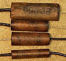
Wax/Paper Tubular Capacitors
All except one of the original paper-wax capacitors were cardboard tubes sealed on both
ends with tar. After each one was removed from the radio, the lead lengths and
type and
any use of insulating sleeving were noted so that lead dress and appearance could be
maintained. Restuffing these early RCA/GE capacitors is quite messy. Here
is my process for the capacitors with cardboard tubes:
- The capacitor is held and rotated using one of its leads using needle
nosed pliers while the tube is heated using a heat gun to soften the
tar.
- The tube is held using paper towels while the contents are pulled out one
end. In most cases, both leads as well as most of the tar came out as
a unit. In some cases the leads pulled out and the contents had to be
pushed out using a small screwdriver.
- Any remaining tar was removed from inside the cardboard tube, and the
outside of the tube cleaned using lacquer thinner.
- If the required lead length on either end exceeded the length of the
replacement axial film capacitor, suitable bare buss wire was attached to
the replacement capacitor close to its body, so that the splice would be
inside the cardboard tube after restuffing. Some of the capacitors
used insulated wire of varying colors rather than bare leads.
- The replacement capacitor was then wrapped with strips of paper towel to
center the capacitor in the cardboard tube and prevent it from falling out.
- The ends of the tube were then sealed using rosin salvaged from servicing
RCA Radiola Superheterodyne catacombs.
- One of the capacitors (the top one in the left photo below) looked like a
block of tar wrapped in a thin paper wrapper. Here
is my restuffing process for this type of capacitor.
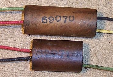
Two capacitors contained multiple capacitors.
One such capacitor (RCA part 69071) contained two capacitors (C1 and C25) and had three
leads. Another (RCA part 69070) contained three capacitors (C12, C13 and C27) and had four
leads. The leads for these capacitors were insulated hookup wire rather than
solid buss wire. The cases were normal tubular or oval cardboard, and the ends
were sealed with tar. If was not obvious what these capacitors were until they
were removed from the radio, since their use was not documented on the RCA
connection diagram. As their leads were disconnected, careful notes were
taken. When compared to the schematic, they were eventually identified. This was
quite difficult, and I started by first removing and identifying all the single
paper capacitors then figuring out what was missing. A missing C24 made this
harder. The restuffing process for these was the same as with single
capacitors, except that interconnected axial tubular film capacitors and hookup
wire was used.
Restuffed Single Paper Caps
|
Restuffed Multiple Paper Caps
|
 |
 |
Filter Capacitors
The original filter capacitors had been removed.
Fortunately I had photos of the original capacitors I took from another example
of this radio which was destroyed in shipping. There were originally two cardboard cased capacitor used,
each containing either two or three electrolytic capacitors. The schematic
in Riders shows the internal connections and wire colors for these
capacitors. I was able to reproduce suitable cases for them made from thin
cardboard similar to the kind used for writing tablet backs. Their measurements
were obvious from photos and from the location of mounting and wire lead holes
on the chassis. The left capacitor (viewing from the radio back) originally contained two 8mfd
capacitors (C22 and C23). The reproduction case was restuffed with two 10mfd/450 volt
electrolytics. The right capacitor originally contained a 4mfd, 8mfd, and
10mfd (low voltage) capacitor. C21, a single separate 8mfd capacitor had been
replaced by a modern unit. I had no idea what the original capacitor looked like
or its size. According to the RCA connection diagram, it was originally mounted
somewhere under the chassis.
I decided to cheat a bit and install C21 inside the case with
C22 and C23. Again, I used a 10mfd/450 volt electrolytic. In
reality, both C21 and C22 could have been rated at 160 volts, and probably were
in the original radio. These capacitors form each side of the voltage
doubler. In order to accommodate C21 I added a third lead to the left
filter capacitor: a green lead which was routed to pin 4 (cathode) of the 25Z5
tube.
I also decided to include the missing C24 (0.1mfd) in the right,
smaller filter case, just in case it might be needed. Recall that it was
not found under the chassis, and I did not know if it had been removed during
the filter capacitor replacement or a production change. A 0.1mfd/630 volt film
capacitor was connected from the + lead of C28 (the B+ output filter) to B- (C18
and C26 negative). For C26 (4mfd) I used a 4.7mfd/450 volt electrolytic. For C28
I used 10mfd/450 volts. For C18 (10mfd) I used a 10mfd/50 volt electrolytic.
The length of each lead wire was calculated by running some
trial routings from the chassis holes to where the lead connects. Extra length
was added for connections to the new capacitors inside the case. The new
leads were connected to the new filter capacitors using the RCA diagram.
Insulating spaghetti tubing and shrink tubing was used to prevent shorts. The
groups of capacitors were then wrapped with strips of paper towels to stabilize
the assembly in the cardboard case. I then added melted rosin from the open
bottom of each case to stabilize the assembly. The exiting lead wires were first
wrapped with tape in order to center them and allow passage through the chassis
holes. I did not include a bottom cover on the fabricated filter capacitor
boxes. The bottoms fit tightly against the chassis.
The case color was a problem. I did not want to just leave
the bare cardboard filters as they were. Ideally they would be painted the same
color as the originals (I had a photo of the originals). I experimented with
various paints, toners, and shellac without success. I finally decided to simply
enlarge the photo of the originals, print the photo, cut paper covers and apply
to the outside of the cardboard cases using wood glue. It seemed to work
OK. The result was not perfect, but better than any alternative that I
could think of.
Here are comparison photos of original capacitors and my
reproductions.
Original Filters
|
Reproductions
|
 |
 |
Small Resistors
Two small resistors were out of tolerance by more than 20%.
One was a 20K 1/2 watt dogbone resistor (R3) and one was a 1 megohm 1/4 watt
dogbone (R2). I
collect NOS as well as used dogbone resistors just for this purpose, and buy all
I can find on eBay and at swap meets. I did not have replacements
available that were in tolerance. In this case I attempt to find a
replacement that is the correct size and has the correct measured value (within
20% tolerance) but not the correct value markings! I then repaint the resistor
with the value required using hobby enamel paint. The 20K 1/2 watt resistor
(R3) required one long
lead, which I did not have in stock. So I was forced to splice on a piece
of buss wire. The splice was covered using spaghetti tubing over the entire
lead..
Tubes
The bad 25Z5 tube was replaced. The 6D6 was replaced by a
correct type 78 (the 6D6 is an acceptable replacement). The remainder of the
tubes were left in place.
Other Repairs
Suitable tube shields (three) were installed.
The non-original antenna lead was cut in half and re-used, but connected and
installed per the connection diagram.
Testing and Alignment
Once the radio had been reassembled,
the radio was powered up slowly using a fused Variac. This allows the new filter capacitors to reform. A DVM monitored the B+ voltage. Surprisingly,
the set came alive and worked, even with all the work done under the chassis!
The set was then aligned per the RCA instructions in Riders - no surprises. The
set worked on both bands, and was very sensitive. Volume control action was
smooth, but since the set did not have AVC, it must be changed while tuning. The
so called short wave band picked up quite a few stations, but only the in center
of the tuning range (the specs say the range is 2.4 to 2.5mHz). The radio was
NOT tested on DC.
Tuning this radio is very difficult since there is no reduction drive - the
small tuning knobs turns the tuning capacitor directly.
Cabinet
One side of the cabinet had started to pull away. It was reglued and
clamped. The cabinet was vacuumed inside and out. I found out during the
clean-up after gluing that the finish would be removed with even small amounts
of water! Fortunately, only the edge of one side was affected. A test in a small
area with GoJo,
my usual cabinet cleaning method, was performed and also found to damage the
finish. So the cabinet was left as is.
Restoration Results
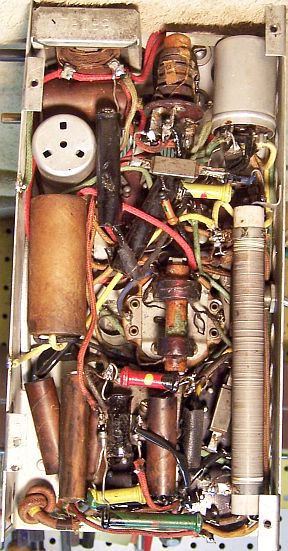
Chassis Bottom Before
|
Chassis Bottom After
|
 |
 |

Rear Chassis After Restoration - Repro/Restuffed
Filter Caps
Tube Shields and AC/DC Switch Replaced
|
|
|

