General Electric Model K-80/RCA 140 Restoration
 |
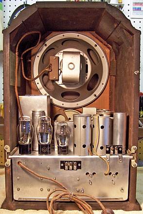
The General Electric Model K-80 (the same chassis was also sold as the RCA
Model 140 and Westinghouse WR-30) is a large elaborate gothic tombstone radio. There is a 4-band
version and also a 5-band version with Long Wave (for export models). The
power transformer is
also capable of operation at 240 volts for export. My example was
the 4-band version and setup for 120 volts, 50-60 Hz.
The
circuit is an 8-tube superheterodyne with push-pull Class B audio output and two
stages of tuned RF amplification on the highest short wave band (4 gang
tuning capacitor). It uses 2.5 volt tubes.
The radio had seen minimal servicing in the past and most original
parts were still in place. This being the case, I
decided to try and retain the original top and bottom chassis appearance if
possible.
The schematic and a partial parts list for the radio can be found on Nostalgia
Air. |
My
antique radio restoration logs
Previous Servicing
-
One original can type filter capacitor C59 had been replaced with a
similar unit.
-
The other original can type filter capacitor C60 was still in place, but
its positive lug had been cut free and a tubular replacement capacitor tacked in.
-
All tubes except the 80 rectifier were RCA/Cunningham branded and
were likely ORIGINALS (all had similar engraved bases).
-
All original paper capacitors and resistors were still in
place.
Cleaning
I normally clean the chassis before starting restoration.
I first blew off the above and below chassis dust with an air compressor.
After the tubes and shields were removed, the chassis was initially cleaned
using various brushes (which barely dented the crud!) The chassis was then partially disassembled for access and cleaning as explained
below.

The chassis and top components were cleaned using GoJo, steel wool, and
toothbrushes. The tuning capacitor was cleaned with soap,
water, and toothbrushes and then dried using a heat gun and lubricated.
The dial drive vernier mechanism was removed, disassembled,
cleaned, and lubricated.
Survey
These radios are VERY difficult to service. Most parts are
buried under the complex bandswitch and RF coil assembly or are mounted on
terminal boards. This RF assembly
must be removed in order to gain access to buried components. Rider's
Manuals does explain how to disconnect the 15 leads from the chassis to the
assembly (but there are a few errors - so take good notes and photos!)
Most of the leads connect to various points on the chassis bottom, but a few go
through the chassis to the tuning capacitor. The large terminal board, the
detector plate choke, B+ filter choke, audio output transformer, and driver
transformer must also be removed in order to access parts underneath them. Needless to say, you must make careful
notes as to where each lead goes and its color (I use marking tags to identify the
leads, since the color is not obvious in most cases). Try and
keep the leads that go through the chassis to the tuning capacitor
together. Also, do not change the lead dress or shape of any wiring from
the RF assembly (that will make reassembly difficult and could also interfere
with the re-installation of the coil shield).
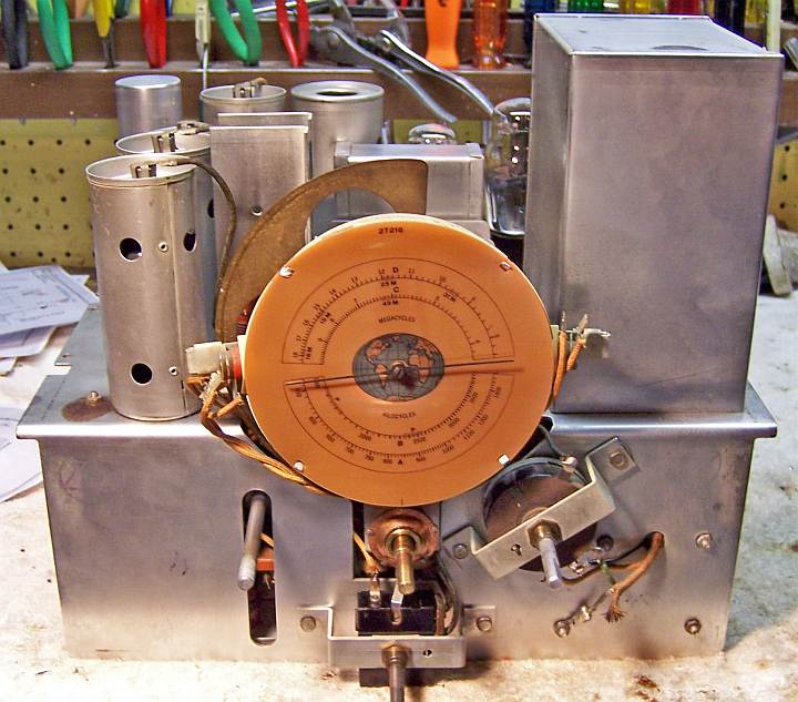
I also removed the tuning capacitor and dial mechanism, the
short wave antenna coil L39/L40, as well as the capacitor pack and filter
capacitor cans. I now had access to all under chassis components for
measurements and replacement if needed, and the top chassis was clear for cleaning.
My usual restoration procedure is to make a complete
survey of the condition of all components and repair all items before the radio
is tested. I assume that all paper and electrolytic capacitors are leaky and thus should be
replaced (I always "restuff" the original components if possible).
-
The power transformer was OK. It drew less than 10
watts unloaded, and all voltages were correct (the high voltage was balanced
on each side of the center tap).
-
The speaker field, cone, and voice coil were OK.
-
All RF coils were OK.
-
Both IF transformers were OK.
-
The filter choke and detector plate choke were OK.
-
The audio driver transformer and output transformer were
both defective - open primaries.
-
The original power cord had a break near the chassis and was
very stiff. It appeared usable.
-
The original speaker cable was OK.
-
11 original dogbone type resistors were out of tolerance
by 30-100%.
-
All tubes checked either good or slightly weak. The
type 80 was likely a replacement (Arcturus brand), but the remainder were
likely original RCA/Cunningham.
Restoration Strategy
Since almost all of the original parts were still in place, and
since this was going to be a "keeper", I decided to try and retain the
original top and bottom chassis appearance if possible.
Repairs
Resistors
The radio uses
"dogbone" type resistors. Quite a few (11) had drifted out of
acceptable tolerance range, and would have to be replaced. In most cases,
I would replace an original resistor only if it was not within +/- 20%. In this radio,
many resistors were enclosed in insulated sleeving because of the close
proximity of the parts. So I decided to replace any defective "dogbone"
resistors that were in sleeves with standard 1 watt carbon composition
resistors, since the replacement would not be visible. Any "dogbone"
resistors that were visible would be replaced with the same type resistor.
I keep a stock of NOS and used "dogbone" resistors, and buy all I can
on eBay and radio swap meets! Of course, most of these resistors, even NOS resistors, have also
drifted in value and no longer have their marked values. My solution is to
find a replacement resistor of the correct value and size as measured (ignoring the
markings), and then repaint it to the needed value codes using enamel hobby
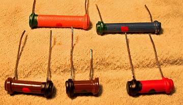
paint! In the case of this radio, only FIVE "dogbone" resistors
that were visible had to be replaced. It is also possible to make a
reproduction "dogbone" resistor using a modern carbon composition
resistor inside a molded cover made from J. B. Weld epoxy.
 |
|
Repainted Dogbone Resistors |
Electrolytic Capacitors
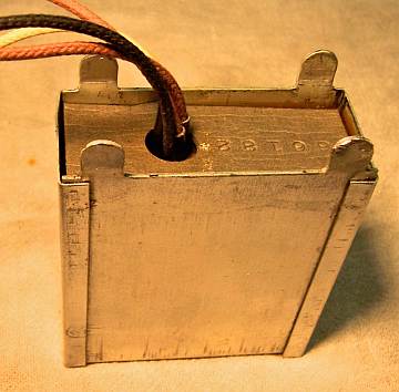
The
3-unit capacitor pack (C12, C49, C56) would be restuffed with new electrolytics. It
contains two 10mfd low voltage capacitors and one 4mfd high voltage
capacitor. It was restuffed with 10mfd/50 volt and 4.7mfd/450 volt
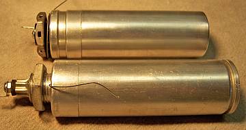
electrolytic capacitors. The can
type filter capacitors would also be restuffed with new electrolytics. The
18mfd unit (C59) was restuffed using a 22mfd/450 volt electrolytic. The 10mfd
(C60) was restuffed with a 10mfd/450 volt unit. The
replacement can type capacitor had wire leads rather than a solder lug. The leads were removed and a
solder lug installed retained by a screw. The original can had its
terminal lug cut off. It fortunately would have been VERY difficult for a
repairman to remove the can, so it was left in place (otherwise it may have been
removed and tossed or replaced). A solder lug was
attached with a screw after the remnants of the original lug was removed. All
the paper capacitors would be restuffed with modern 630 volt film capacitors.
 |
|
Capacitor Pack - Rebuilt With New Electrolytics |
 |
|
Rebuilt Filter Capacitor Cans (the bottom one is original) |
Paper Capacitors
All paper capacitors were rebuilt in their original cases
using modern 630 volt film capacitors in order to maintain the original
under-chassis appearance. The radio used two type: most were typical early
RCA tubular capacitors, which have no markings other than the part number.
The other type look like a block of tar wrapped with paper. They have no
markings that I could read. Here
is how I restuff the tar block types.
In both cases, I remove the capacitor from the radio by unsoldering its
leads. The lead lengths and any insulating sleeving lengths are then
noted. I take notes of which lead goes where in the radio, and identify
the capacitor using marking tags (which note the part identification and the
location in the notes where it was removed).
The tubular types are very easy to restuff. I simply pull the leads out
of each end. This usually also removes most of the tar used to seal the
capacitor. The capacitor foil roll is then pushed out one end. Any
tar remnants are removed using an Exacto knife. I then place the cleaned
up cardboard cover over a small alcohol lamp to melt any wax or tar left on the
outside, and then wipe it off with a paper towel. Leads of the replacement
axial film capacitor are then extended if needed (referring to the original
component lead lengths). The replacement capacitor is then wrapped in a
piece of paper towel cut to the width of the replacement capacitor. Enough
is wrapped around the capacitor to hold it securely inside the cardboard tube
and to center it.
Then ends of the restuffed capacitor are then sealed using melted rosin salvaged
from RCA catacombs, which melts are a fairly low temperature. Other
restorers have used
hot melt glue or even caulk to reseal capacitors. The original insulating
sleeve, or a replacement (black spaghetti tubing) is then installed.
Finally, the capacitor is tested before installation in the radio.
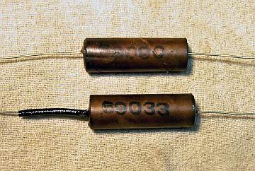 |
| Restuffed Tubular Capacitors |
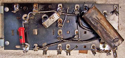
Terminal Boards
Most of the resistors and quite a few capacitors in this radio are mounted on
two terminal boards. In this radio, it was not necessary to remove the
small terminal board, since only two components needed replacement and were
accessible with the board in place. The large terminal board had to be
removed to gain access to components underneath. All the capacitors were removed
and restuffed. All resistors that had drifted too far in value were
removed. The board was then cleaned, and replacement components
reinstalled.
| Large Terminal Board, Top and Bottom after servicing. |
 |
 |
Tone Control and Switch Repair
The tone control was of the Allen-Bradley BradleyStat type. The
resistive element was intermittent and the switch was not working. To
repair it:
- The metal back cover was removed - it simply snaps off.
- The wiper was removed - it can be pulled from its pivot (careful not to bend
it).
- The wiper and resistance element were cleaned with lacquer thinner on
Q-tips. Note
that the wiper does not directly contact resistance element, which is wound with
circles of wire. Use a minimum amount of lacquer thinner so as
not to damage the resistance element. Just remove the dried grease (I
do not replace the grease).
- The switch contacts on the control were first cleaned using lacquer thinner on
a Q-tip and a pipe cleaner, followed by Caig DeOxit and a final cleaning
using lacquer thinner.
- The wiper was reinstalled and and the control and power switch tested for
functionality and the back cover reinstalled.
Audio Driver Transformer
This radio uses push-pull Class B audio output using a type 56 driver and 53
(6N7) output tube. The driver transformer had an open primary winding. In
this application, the transformer operated in STEP DOWN mode, and must handle
some power when driving a class B stage (which draws grid current). An ordinary
A-53C type audio interstage transformer CANNOT be used. I previously
restored an RCA model 140 which had a GOOD driver transformer. I always
take the time to measure the actual ratio of all driver transformers I
encounter. I have documented my findings
in this table. The ratio was measured as 5.2245:1, primary to 1/2 secondary.
I measure transformer ratios using a vintage HP200A audio oscillator which delivers
a clean, stable high power sine wave. I normally drive the primary at about 12
volts at 400Hz. By measuring the primary and secondary voltages using my
DVM, the ratio can be calculated.
The Hammond 124E transformer fits this requirement very closely if used backward.
The dual secondaries were connected in series aiding (135K ohms impedance) and
used as the primary. The primary (now used as the secondary) is rated at
15K CT ohms impedance. The ratio is thus 6:1 primary to 1/2 secondary used
in this manner (original was 5.2234:1). The transformer is rated at 5 watts, so it would have no
problem delivering enough power to the 53 tube grids. And also important,
with its mounting tabs removed, it would just fit inside the original transformer
case.
The original transformer was removed from its metal case by positioning the
transformer upside down (resting on its studs) on an old foil-covered baking
sheet in a 275 degree oven. After about 1 hour, the transformer and most
of the tar could be removed. The remainder of the tar was removed
mechanically, then by soaking the case in paint thinner over night and then
cleaning off the residue with more paint thinner and old tooth brushes.
The original transformer leads were salvaged and spliced onto the replacement
transformer.
 |
| Restored audio driver transformer with Hammond 124E |
Audio Output Transformer
The audio output transformer had an open primary (both sides). I had previously
restored an RCA 140 and had measured the output transformer ratio, but that
transformer was NOT original. So I decided to go to my tube manual for the
required plate-to-plate load impedance. The speaker voice coil impedance
was documented in Riders as 4 ohms. I also measured it as 3.8 ohms DC and
4.152 ohms impedance. I measure speaker voice coil impedance by placing the
voice coil in series with a low value resistance (5-10 ohms, which is carefully
measured using my DVM) and connected to my vintage HP200A audio
oscillator. With about 1 volt across the series resistor and voice coil,
and measuring the voltage across the coil and the resistor, the impedance can be
closely calculated. I normally use 400Hz for this test.
Consulting the tube manual, a type 53 tube (6N7) operating in Class B with
300 volts on the plate should see a plate to plate load impedance of 8000
ohms. The required output transformer ratio needed is thus 44.7 to
1. The 53 tube can deliver up to 10 watts maximum, and the plate current at
zero signal is 35ma.
Looking at available Hammond output transformers, the 125C (8 watts) and 125D
(10 watts) could be configured to provide a load of 8800 ohms to 4 ohms.
The 125C mounting centers were the same as the original. The 125D was WAY
too large. The transformer is mounted between the filter choke and driver
transformer on the rear chassis, so space (width) is limited. I was also concerned that the secondary lugs on the 125C transformer may stick out too far
on one side (the Hammond specification sheet gives the TOTAL width, but not the
width on each side of the center line of the mounting holes). Instead, I
opted for the Antique Electronic Supply
P-T291 transformer which would match 4 ohms to 9000 ohms, had the correct
mounting hole spacing, and since its secondary terminals were vertical, would fit between
the choke and driver transformer. It was also rated at 8 watts.
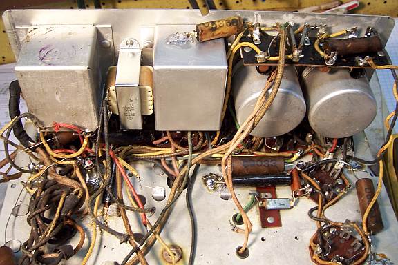 |
| Main chassis after all capacitors restuffed, transformers
replaced. Any drifted resistors replaced. |
 |
| Main Chassis Complete - Terminal Board Reinstalled -
Ready for RF Subassembly |
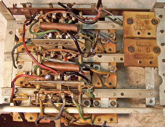 |
| Recapped RF Section ready for re-installation into the
main chassis. |
Tuning Mechanism Vernier Drive
The tuning shaft was slipping and would not rotate the tuning
capacitor. This is normally due to hardened grease and dirt in the vernier
drive assembly. The assembly was removed from the tuning capacitor drive
shaft and disassembled. One needs to be VERY careful with the bent-over
tabs that hold the unit together! They will break off in a
heartbeat! Bend them VERY carefully and slowly, and only enough to free up
the parts. Be careful to note the order of parts in the assembly, and do
not lose the ball bearings! All parts were then cleaned with lacquer
thinner and brushes. A light grease was then applied to all surfaces (I
use a rapidly dwindling supply of Teletype grease!) and the unit
reassembled. It then worked perfectly.
Power Cord
- The original power cord was cut at the break near the chassis grommet and
reinstalled. It was pulled back into the chassis, a new knot tied, and
then spliced onto the original stub inside the chassis.
Testing
After the radio was completely reassembled, power was applied through a
wattmeter and fused Variac. Power was brought up slowly while monitoring
the B+ voltage and wattmeter. Normal B+ was reached with 115 volts
input. The radio came alive and worked well - no assembly errors!
The dial calibration was even correct on the broadcast band.
The radio was then aligned. This radio has an individual trimmer for
each and every RF coil (13) plus two padder capacitors for the first two bands. But the adjustment
screws are all in the CENTER of the coils. So one must use a non-metallic
tool to do the alignment. A plastic tool I had would not reliably turn the
trimmer screws. I was forced to use a plastic tool with a small metal tip
on the end. It worked, but did affect the tuning. After some
experimentation, I found that I could peak an adjustment, note the output meter
voltage, then tweak the trimmer one way or the other until the voltage was the
same as the previous reading with the tool removed from the coil.
The radio performs very well - it has excellent
sensitivity (due to the tuned RF stages) and has good tone also. It
is especially hot on the high short wave band, where there are two stages of RF
amplification. It is difficult to tell if the two replacement audio
transformers affected the tone, since I have no original to compare with.
Restored Chassis


Cabinet
The cabinet was in excellent shape. It was cleaned with GoJo hand cleaner
and 00 steel wool, followed by a coat of Johnson's Wax.