The schematic for the GE J-71 can be found on Nostalgia Air. Any part numbers will refer to numbers on that schematic.
|
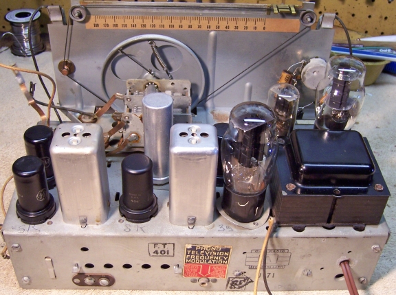
The GE J-71 is a large 7-tube AC Superhet
circuit table radio that receives the broadcast band and two short wave
bands. It features automatic or push-button tuning and built-in loop
antenna for both broadcast and short wave. The radio had seen a
minimal amount of servicing in the past. I decided to try to reverse any previous
repairs to the extent possible.
The schematic for the GE J-71 can be found on Nostalgia Air. Any part numbers will refer to numbers on that schematic. |
My antique radio restoration logs
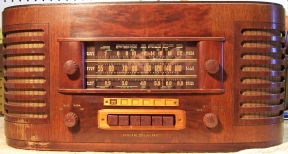
This radio was purchased on eBay. My example cabinet was presentable, with no damage or serious scratches or dings. It had all its original knobs and grille cloth, and the cloth was in good condition. The power cord was original, but worn in areas in places with bare conductors exposed. The radio had been very poorly packed. When received, the volume control shaft had been bent over, which pulled the front of the volume control loose. The speaker magnet had been moved and was almost free of the speaker frame. It was later found that the movement of the magnet had pinched the voice coil, which was immovable. There was also some damage to the cabinet and to the grille. An insurance claim was submitted to the US Postal Service. The claim was approved, and received a check for the full amount of the item and postage (less insurance). So basically, the radio was free. At the time the claim was submitted, repair and re-coning of the speaker and replacement of the volume control could almost exceed the value of the radio.
The radio had seen a minimal amount of repair in the past, and all repairs were far in the past, judging from the components used. The combination power and tone switch (4 position) had been replaced by a standard 100K potentiometer with switch. The control thus would only act as a variable treble cut type tone control. One original capacitor had been changed to make this control work properly. But all the rest of the capacitors, including the filter capacitor, were original. All original resistors were still in place. The power cord was original, but bare in places and not usable. Only two of the tubes were branded General Electric, and thus most or all tubes likely were replacements. The 6J5GT tube had been replaced with a 6J5 metal tube. The 6Y6G tube had been replaced with a 6Y6GT.
My usual restoration procedure is to first make a complete survey of the condition of all components. The survey results guide my restoration strategy. If major and unique components are defective or missing and cannot be restored or replaced, I may elect to sell or keep the radio for parts rather than to restore it. I always assume that all paper and electrolytic capacitors are leaky and thus should be replaced (I always "restuff" the original containers if possible). Any mica capacitors are assumed OK until testing proves otherwise. I never apply power to an unrestored radio, even through a variac or "dim bulb" tester.
Nine resistors were out of tolerance (more than +/-20%). All were 1/4 watt dogbone type resistors.
The output transformer was OK.
The speaker cone was OK, but the voice coil was trapped by the pole piece due to the magnet being knocked out of position during shipment. As received, the speaker did not work.
The volume control shaft was bent over, pulling the front of the control loose from the body of the control (the control was tab mounted rather than mounted by a shaft bushing).
The power transformer was OK. The high voltage was balanced across the center tap with 20 volts applied through a variac. With full power applied (no tubes present), the wattage consumed was less than 10 watts. A transformer with shorted turns will draw excessive power and will heat up. I use a real analog watt meter for these tests.
All RF coils and transformers were OK.
The IF transformers were OK.
All tubes were good except for the 6SQ7. The triode section and one diode was OK, but the other diode tested very weak.
Wiring was a mixture of cloth and rubber covered wire. Some rubber covered wire would likely have to be replaced is disturbed.
Both of the pilot lamps were burned out.
The rubber power cord was original, but bare conductors were exposed in several places. The plug had likely been replaced. The cord was NOT safe to use.
The volume control knob had been broken (internally) in shipment.
Before starting any repairs, I had to address the potential showstopper issues of the speaker, volume control, and non-original power and tone switch. The speaker could be very expensive to repair. I contacted several speaker repair/re-coners in order to obtain estimates for the insurance claim. Estimates varied from $30 to $92 plus shipping both ways. If the voice coil was creased or damaged, then a re-cone would be needed (the higher of the two estimates). Of course, it would likely be possible to find a suitable 6.5" PM pincushion type replacement speaker for less money. But then, the radio would no longer be original, and this radio uses inverse feedback from the speaker back to the audio driver stage. The mounting centers would have to be exact to avoid having to use a kludge adaptor panel. I removed most of the old glue that previously stabilized the speaker magnet. I then moved the magnet around while testing the voice coil for movement. I only used a screwdriver to move the magnet, avoiding hammer blows which could reduce the magnetization. Eventually the voice coil did free up, but at this point I did not know if it had been damaged or was rubbing. The speaker was connected to an old solid-state AM-FM radio for testing (which originally used external speakers). The speaker appeared to work OK, although likely not perfectly. When mounted in the cabinet, it sounded great, even at high volume levels! There was no noise or rattle noticed. The magnet was then secured in place using GC Service Cement.
The volume control was freed from the chassis by untwisting its mounting tabs. The front of the control was then reattached to the body of the control by re-securing the retaining metal tabs. When tested using an analog VTVM, the control seemed to operate smoothly throughout its rotation, and its value was correct. So for now, the control seemed OK (pending testing upon completion of restoration). This was fortunate, since a tab mounted tapped control would be expensive to replace.
I then removed the non-original power and tone control and an associated non-original capacitor. The original part was a 4-position single pole rotary switch with an attached AC power switch. Checking my switch parts stock, I found a new Centralab CRL 1483 tone switch which was a 2-pole two to five position shorting type rotary switch. While larger in diameter than the original, the switch did fit in the chassis and could be configured for four positions. One set of contacts would switch the AC power, and the other set would control the tone (hopefully, no AC hum would be introduced). I replaced the chassis in the cabinet and installed a chicken-head knob in order to check the switch rotation against the cabinet labels. It matched up very well! The next challenge was to file a notch in the front of the shaft for the push-on pointer knob. The position of this notch was obviously critical. There was very little room for re-positioning the switch so that the knob pointer would line up with the cabinet labels. I managed to get fairly close by comparing the angle of the planned notch position with that of the band switch shaft (also four positions). The notch was marked and cut using a hack saw and then filed smooth.
The volume control knob was repaired using epoxy. The repair was inside the knob and thus not visible. Fortunately the knob spring was found in the shipping box and reinstalled.
Since all showstoppers to restoration had now been resolved, I proceeded with the electronic restoration. All tubes were removed and dust was removed using an air compressor, tooth brushes, and a vacuum cleaner. Before starting repairs, I took photos of the chassis top and bottom so that routing of wiring and component placement could be restored. Lead dress is often critical in radios.
When I replace a component, I always remove the original part completely from a terminal. Other components such as mica capacitors and in-tolerance resistors connected at the terminal are protected from heat using old medical clamps (hemostats). Excess solder is then removed using a solder sucker in order to expose terminal holes for reattachment of the rebuilt or replaced component.
Only one original wax/paper capacitor C19 had been replaced. None of the original capacitors had manufacturers names indicated. They all had a large number in a circle, and a part number such as K12J33-403. The missing capacitor was 0.002mfd, voltage unknown (likely 400 or 600 volts). I found a similar type in my dud capacitor stocks. However, I did not have a 0.002mfd. So I used a 0.004mfd. It was restuffed using a 0.0022mfd/630 volt film capacitor. The remainder of the original capacitors were also restuffed using new axial film capacitors. Here is my tubular capacitor restuffing process.
The original filter capacitor was still in place. It was a three section twist lock type capacitor: 30mfd, 15mfd, and 10mfd all at 250 volts working and 350 volts surge. It was restuffed using 33mfd, 15mfd, and 10mfd 350 volt radial capacitors using the following technique:
 |
Original filter capacitor, restuffed. |
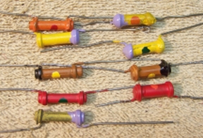
All resistors in the set were dogbone type resistors. Nine resistors were out of tolerance by more than 20%. I maintain a stock of NOS and used dogbone resistors, and buy all I can find that are reasonably priced. I also NEVER throw away a used dogbone resistor, even if out of tolerance. Searching my stock, I found suitable replacements for all nine (selected by measured value and size rather than marked value, since most resistors of this age will have drifted, even if NOS). These were then repainted to the correct values using hobby enamel paint. Here are the repainted replacement resistors:
The power cord was replaced using a new vinyl cord. The 6Y6GT tube was replaced with the correct 6Y6G type. The 6J5 metal tube was replaced with the correct 6J5GT type. The 6SQ7 tube with the weak diode was replaced.
The cabinet was vacuumed and then cleaned using GoJo (the white type, not pumice) hand cleaner and 00 steel wool. The dial glass was also removed and cleaned.
Once the radio was reassembled and the tubes installed, power was brought up slowly using a variac. A DVM monitored the B+. The radio came alive immediately and worked. The radio was then aligned. There are extensive alignment instructions in Riders. Alignment is difficult with the radio in its cabinet. There is very little vertical room for alignment tools. If aligned outside the cabinet, the loop antenna must be removed from the cabinet and placed close to the chassis (maintaining the same distance as when the chassis and loop are installed in the cabinet). In order to adjust the automatic tuner buttons, the chassis has to be removed from the cabinet!
The damaged volume control worked perfectly. There did not seem to be excessive hum pickup from the replacement combination tone and power switch. The speaker sounded fine.
The built-in loop antenna worked OK for the broadcast band. But there was not much reception on the two short wave bands using only the loop antennas. Fortunately, the radio will accept an external antenna (and ground).
Most of my restoration objectives were met, but not all. There was no intention of restoring the set to factory new appearance! My objective is usually to reverse any prior servicing and make the radio appear to have never been repaired. I do not go so far as to artificially "age" solder joints, as do some collectors! Nothing gives away a restoration faster than bright and shiny solder joints. Here are some of my "misses":
Chassis Before Restoration |
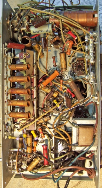
Chassis After Restoration |
 |
 |