Grunow 460 Small Cathedral Restoration
 |
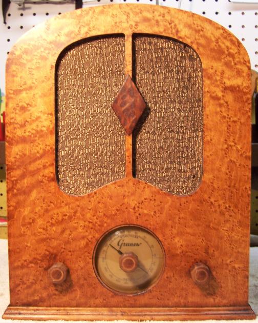
The Grunow 460 is a small 4-tube non-AVC superhet circuit cathedral
style radio with a distinctive curly maple veneer cabinet. Grunow
was a trade name of the General Household Utilities Co. The 460 only receives the broadcast band and requires an
external antenna (and ground). The radio had seen minimal servicing in the past and most original
parts were still in place. This being the case, I
decided to try to reverse any previous servicing and retain the original top and bottom chassis appearance if
possible. The radio was purchased on eBay. The seller stated that it
"needs work" - that was a bit of an understatement!
The schematic and a partial parts list for the radio can be found on Nostalgia
Air. Any part number references in the text below reference that
schematic.
|
My
antique radio restoration logs
Previous Servicing
-
The original filter capacitor bank (a cardboard cased unit
mounted under the chassis) had been removed and several modern capacitors
tacked in. The original was a dual 8mfd unit at 350 volts. The
replacement were four 4.7mfd @ 450 volts (two 4.7mfd in parallel on each side of the
speaker field).
-
All resistors and paper-wax capacitors were original
-
The line cord and plug were original and even usable with
repairs.
-
Three of the tubes were branded RCA or RCA/Cunningham and
may have been original. The 6A7 was a replacement.
Survey
This radios is difficult to service with limited access to
several parts due to the rather small chassis and the tuning capacitor being
mounted under the chassis. My usual restoration procedure is to make a complete
survey of the condition of all components and repair all items before the radio
is tested. It may not be possible to test high value resistors because of
leaky capacitors. In this case, one end of the resistor must be
disconnected or leaky capacitors disconnected. The eBay seller made no statement about the electrical condition
of the radio. Like in Zenith radio schematics, all parts having the same
part number use the same call out in the schematic. So there are multiple occurrences
of R7, C11, and C14 on the schematic. Before doing the survey I first make
these occurrences unique by adding a suffix letter (A, B, C etc.)
-
The power transformer was defective! The primary winding was
open, and the high voltage secondary measured a very low and asymmetrical
resistances across the center tap: 8.3 ohms on one side and only 88 on the
other side. The high voltage winding obviously had shorted turns. There
were no external signs of burning or leaking tar. However during
cleaning, the material on the chassis around the power transformer was very difficult to
remove even using lacquer thinner. It may have been some sort of wax
that had leaked from the transformer.
-
The unusual tapped speaker field coil, cone, and voice coil were OK.
It is very difficult to replace a speaker having a tapped field coil, since
in this case the tap location determines the output tube grid bias.
-
The antenna and oscillator coils as well as the IF
transformers were OK (all were tested for resistance and/or
continuity).
-
The original cloth covered power cord and plug were OK but
had one area that would need to be repaired to be safe.
-
The original speaker cable was OK.
-
There were two wire wound resistors (one a tapped Candohm
type unit). Both were OK. All remaining resistors were old style dogbone types.
All were significantly out of tolerance,
-
All supplied tubes tested good (the 6F7 triode section was
marginal).
-
The wire wound volume control was bad. Its total resistance
was unstable and had only intermittent contact from the center terminal to
either end terminal as the control was rotated.
-
The power switch was initially bad, but responded to a good spray of
GC Big Bath cleaner through holes in the housing, followed by repeated
operation.
-
The 6F7 grid cap lead from the first IF transformer was
frayed and had deteriorated. The shield would have to be removed in order to
effect correct repairs (vs. simply sliding on spaghetti tubing or shrink
tubing).
Cleaning
The dust was first removed using an air compressor. After removal of the dial assembly and tuning capacitor, the
tacked in filter capacitors, the antenna coil and its shield and power transformer, the chassis and remaining top components were cleaned using
lacquer thinner, GoJo (white) Hand Cleaner, 00 steel wool, and
toothbrushes.
Restoration Strategy
Since almost all of the original parts were still in place, I decided to try
to retain the
original top and bottom chassis appearance to the extent possible. All
original capacitors would be rebuilt in their original containers (restuffed). Any out of tolerance
resistors would be replaced with the same types if available. The power
transformer would have to be replaced, hopefully with a similar unit. I would
attempt to reproduce this missing filter capacitor block - chassis mounting
holes and a shadow on the chassis indicated its size and shape.
Repairs
Power Transformer
The original power transformer was removed from the chassis for
inspection. It was hopelessly burned inside!

The primary winding was open, and the high voltage secondary
indicated shorted turns - one side of the center tapped winding measured only 8
ohms, and the other side 88 ohms. It was not clear what caused the
original failure, since the filter capacitors had been replaced recently. There
were no shorts from B+ to ground, even though all the paper-wax capacitors were
original. There were no shorted or gassy tubes. It could be that the
previous owner replaced the filter capacitors without first testing the
transformer. This is apparently quite a common practice with new or
inexperienced antique radio collectors.
The original transformer supplied three 6.3 volt tubes plus a
pilot lamp (1.75 amps total), and a 5 volt 2 amp rectifier. It was a horizontal mount unit. I
just happened to have a parts chassis for a Stewart Warner model 3043 in
stock. The transformer in that chassis was good, and was a horizontal
mounted unit also. It supplied four 6.3 volt tubes plus a pilot lamp, and a 5
volt 2 amp rectifier. The current draw on the filament windings for both
sets was identical even though the tube count was different (the Stewart Warner
used a 6K6 output tube, and the Grunow uses a 42). So I decided
to install the replacement transformer to replace the original. The fit
was acceptable, although the replacement transformer was slightly smaller than
the original unit.
Tuning Capacitor
The tuning capacitor was cleaned using my old Heathkit
ultrasonic cleaner and dilute ammonia. It would not all fit in the cleaner
at once, so several cleanings at different angles were needed. I normally remove the mica
trimmer insulators before cleaning in order to avoid damage. Before
removing the mica, I note the original position of the trimmer screws on the
clock, then note the number of 1/2 turns to fully tight. This is done so that
the trimmers can be returned close to their original settings after cleaning. The capacitor was then cleaned using
soap, water, and toothbrushes. After drying with a heat gun, the bearings and grounding
fingers were lubricated using automotive distributor cam lubricant.
Volume Control
The volume control was removed from the radio and disassembled.
It was a wire wound type with a fixed resistance mechanical stop. The wiper and spring were
first removed. The rivet holding the center terminal was drilled out and
removed. On the inside, this rivet along with a flat washer retained the
resistance element. The end terminals are not physically attached to the
resistance element - the connection relies on pressure supplied by the retaining
rivet and washer. Any dirt or corrosion will result in an intermittent connection. The
resistance element was then removed and carefully cleaned using lacquer thinner
and a tooth brush. The
wiper, spring, and center rotating contact were also cleaned. The resistance
element was then reinstalled and the rivet replaced using a 4-40 x 1/2" brass
round head machine screw, plus the original flat washer. A 4-40 nut retained the
original center terminal. One must carefully note the orientation
of the resistance element as well as the wiper during disassembly and
reassembly, otherwise the minimum resistance and taper will not be correct (ask me how I know that!) After these repairs, the total
resistance was OK. The minimum resistance measured about 400 ohms, which
seems reasonable (specification is 350 ohms).
Resistors
The radio uses two wire wound resistors, both of which were OK.
All five other resistors were 1/4 watt "dogbone" type carbon resistors. ALL of these
original resistors had drifted out of
acceptable tolerance range, and would have to be replaced. In most cases,
I would replace an original resistor only if it was not within +/- 20% (or
marked tolerance). Any "dogbone"
resistors would be replaced with the same type resistor.
I keep a stock of NOS and used "dogbone" resistors, and buy all I can
on eBay and radio swap meets! Of course, most of these resistors, even NOS resistors,
would have also
drifted in value and no longer have their marked values. My solution is to
find a replacement resistor of the correct value and size as measured (ignoring the
markings), and then repaint it to the needed value codes using enamel hobby
paint!
I was able to find suitable replacement resistors in my
stock of "dogbone" resistors. Here are the repainted replacement
resistors:

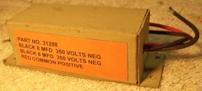
Filter Capacitors
The original filter capacitor block had been removed. The
mounting holes, plus a shadow on the inside rear chassis, indicated its size.
And the Riders documentation indicated its location and height relative to the
power transformer and other parts. The original was a dual 8mfd @ 350 volt unit
with a common positive lead. The capacitor apparently used wire leads. The
revised schematic lists the wire colors used. I was able to fabricate a
cardboard box using cardboard from the back of a writing tablet. Two 10mfd
450 volt capacitors were installed inside the box. The radio requires a
common positive lead and two separate negative leads. The box was spray
painted, and a label fabricated using the correct Grunow part number and
capacitor values. Here is the reproduction capacitor:
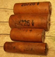
Paper Capacitors
The paper capacitors used have no markings
other than the Grunow part number (which agree with the schematic) and a
"ground" symbol, which I assume means "outside foil".
They were likely made in-house. All paper capacitors were rebuilt in their original cases
using modern 630 volt film capacitors in order to maintain the original
under-chassis appearance. I remove the capacitor from the radio by unsoldering its
leads. The lead lengths and any insulating sleeving lengths are then
noted. I take notes of which lead goes where in the radio, and identify
the capacitor using marking tags (which note the part identification and the
location in the notes where it was removed). Here
is my restuffing process for this type of capacitor. And here are some
examples of restored Grunow capacitors from this radio:
Other Repairs
The pilot lamp was replaced with a #40 bulb (6-8 volts, 0.15 amp, screw
base). There was no marking as to type on the original bulb.
The line cord had one area that required repairs. The outer cloth
insulation was missing and the inner lead insulation was starting to fray. The
cord was cut at this point, spliced back together, and insulated with heat
shrink tubing.
The 6F7 grid lead from the second IF transformer was frayed and had to be
replaced. The grid cap was removed followed by the IF transformer shield.
The transformer was then removed from the shield - its connections were not
disturbed. A new lead was attached to the coil and the lead routed through the grommet
in the shield. The coil was then returned to its shield, the shield
reattached to the chassis, and the grid cap reattached to the new lead.
Cabinet
The cabinet was in excellent shape. It was cleaned with GoJo hand cleaner
and 00 steel wool.
The
grille cloth was slightly loose. It was re-positioned and reattached to
the cabinet to eliminate sag. The type of cement used allowed careful
localized removal of the cloth in the affected areas. The cloth was
stretched then simply pressed back against the cabinet. The original glue
grabbed it and retained it.
Testing
After the radio was completely reassembled, power was applied through a
wattmeter and fused Variac. Power was brought up slowly while monitoring
the B+ voltage and the wattmeter. The radio came alive and worked - no assembly errors! The radio was then
aligned.
Restoration Results
Most of my restoration objectives were met, but not all. There was no
intention of restoring the set to factory new appearance! My objective is
usually to reverse any prior servicing and make the radio appear to have never
been repaired. I do not go so far as to artificially "age"
solder joints, as do some collectors! Nothing gives away a restoration
faster than bright and shiny solder joints. Here are some of my
"misses":
- Replacement power transformer
- Reproduction filter capacitor block
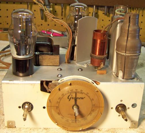
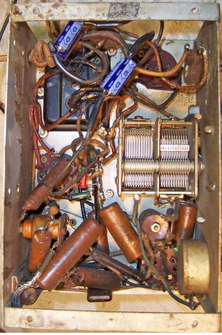
Chassis Before and After Restoration
Chassis Before
|
Chassis After
|
 |
 |
After Restoration Photos