My antique radio restoration logs
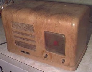
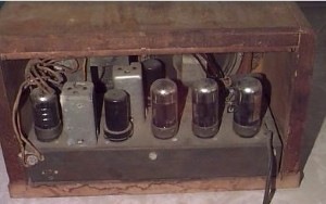
The following documents the restoration of a rare post-war 32-volt farm radio, manufactured by Karola of Minneapolis. No model number was found on the radio, and the manufacturing date is unknown. No schematic appears in Riders or in Sams. The radio was acquired on eBay. Here are the original pictures as they appeared on eBay. Note that there are no knobs, and a hole has been drilled in the top right near the back. Also note the water damage on top and inside the cabinet.
32-volt sets were used on farms before mains electricity was available in rural areas. The electric plant typically consisted of a bank of batteries and a wind charger or engine powered generator. I was interested in this set because it runs 32 volts on the plates, and uses no vibrator supply for high voltage. It also uses three WWII-vintage 28D7 tubes. The 28D7 is a dual pentode with a filament voltage of 28.0 volts at 400ma. It is capable of 100 milliwatts output.
The Cabinet
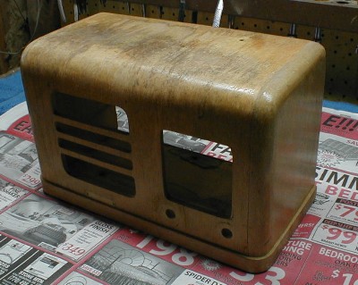
It is hard to imagine what the original finish or knobs would have looked like. There were dark water damage stains on the top and inside the cabinet. The cabinet may have been stripped and refinished at some point in its past. What remained of the finish appeared to be some sort of light fruitwood stain/lacquer. The cabinet is constructed of a white, low quality soft wood with little visible grain. My strategy was to restore the cabinet to a similar color. At one time there may have been a back cover. There were two tacks projecting from each side of the cabinet at the top, and a small rabbet across the top. But there was no sign anything that would have held a cover on the case bottom. Here is a picture of the cabinet before stripping.
There was a hole drilled into the top of the cabinet, which lined up with one of the IF transformer adjustment screws. Interestingly, the metal around trimmer at the top of the IF can had been nibbled away! The grill cloth was not original, and had been replaced by a piece of cloth tacked in with thumbtacks (which penetrated the front of the cabinet in several places). The cabinet was refinished as follows:
Electrical Restoration
The circuit is very unusual. It is a 7-tube superhet with a tuned RF stage (14H7) and 3-gang tuning capacitor. The converter is a 14J7. The IF amplifier is a 12SK7. The second detector and AVC is a 12SR7 (dual diode + triode). The audio amplifier consists of a 28D7 second audio and phase inverter followed by two 28D7’s in push-pull parallel! The parallel push-pull arrangement was implemented in order to obtain adequate audio power from such a low plate voltage.
The filaments of all three 28D7s are in parallel and fed from the 32-volt power input through a dropping resistor. The filaments of the remaining 12 volts tubes are in series parallel, and again in series with the same common filament-dropping resistor. The resistor as found was 10 ohms. Assuming 25.2 volts across the 28D7’s and series-parallel 12-volt tubes, the filament current would be 1.425 amps, so the 10-ohm resistor would drop 14.25 volts! This would mean that the input to this radio would have to have been close to 40 volts! Likely, some hack replaced the original resistor with whatever he had in is parts bin. I replaced the resistor with a 5 ohm 20 watt unit, which would give the tubes the right voltage at 32 volts in. Usually 32-volt sets use battery type tubes in series. This set would draw almost 1.5 amps from a 32-volt battery - not very efficient. A lot of power is wasted in the series-dropping resistor. But I suppose post War 28D7s were cheap at the time (they still are!)
As found, all three of the 28D7’s were open, and one of each series-parallel 12 volt tubes ALSO open. Since the plug on the cord looks like a normal household plug, it is likely that someone plugged this set into 120 volts at some time in the past, to see if it would work! The 32-volt warning (in red) on the back of the chassis was very faded.
Another unusual aspect of this radio is the tuning dial. The scale read 55, 64, 60, 70, 80 etc. The 64 (640) was obviously out of place, but I guess the manufacturer could not afford to re-do the dial scales!
All of the resistors were within 20% except the 28D7 output stage cathode bias resistor (replaced). The rest were left alone. The usual audio coupling caps were leaky, and replaced with modern parts (no attempt was made to conceal this repair).
This radio had been badly botched. The original antenna coil had been replaced with what looks like an antenna coil from an early 30's RCA/GE superhet (it still had a redundant grid cap attached!). As wired, it would never have worked: the primary and secondary were wired in parallel, tuning cap to ground, low end of coils to AVC, high end to antenna as well as the grid to the RF amplifier. Looks like someone tried to repair it and failed. I understand from the antique-radio@yahoogroups.com email reflector that lightening often destroys the antenna coils in these farm sets. I wired the extant coil correctly, but the grid dipper showed that the low end resonated at about 450kHz. So this coil would have to go. The oscillator padder capacitor also appeared not to be original. It looked like it was removed from an IF transformer and a small fixed mica capacitor soldered across it. Also, the existing antenna coil was so large that the radio could hardly be removed from the cabinet. I found a smaller one from my junk box and removed turns until it would resonate at 550kHz with the tuning cap at maximum capacity, and would track to 1700 on the high end. I checked resonance with a vintage Eico Grid Dipper!
The oscillator coil and RF-to-converter coil appear original. The converter input coil seemed to track the broadcast band (as well as I could tell with a grid dip meter). The dial shows the frequency range should be 550-1700Khz.
By feeding a signal generator into the IFs I determined that the tuning range of the two transformers was different! One would peak between 238-347Khz, and the other 320-470Khz. Both appeared original based on wiring under the chassis, but their appearance was different chasis top. Also, I mentioned that someone had "nibbled" away some metal around the trimmer on one of the transformers. I removed both transformers looking for any signs of damage - there was none. So I concluded that someone had replaced one of the transformers with the wrong type: one was probably a 262KHz unit and the other a 455KHz unit! Since I did not know the IF frequency, I looked for other clues.
Testing the oscillator range with the existing padder and tweaking it (as well as the trimmer cap) shows that the maximum tuning range of the oscillator with existing padder is 601Khz (966-1567KHz) - clearly insufficient to track the broadcast band (1700-550 = 1150Khz). The actual range as found was 1076 to 1590 KHz. This would hint that the IF frequency was 455kHz vs. 262kHz. But the existing oscillator padder would have to go. I replaced the oscillator padder with an adjustable mica capacitor that allowed the oscillator to tune from 1005 to 2155kHz. This range, less the 455Khz IF, should allow tuning from 1005-455 = 550 to 2155-455 = 1700kHz. I checked the oscillator frequency by hanging a short clip lead off the hot end of the oscillator feedback winding, and picked up the signal on a nearby Radio Shack DX440 digital radio with the BFO turned on.
I replaced both IF transformers with known good 455kHz units that were virtually identical in appearance to the originals.
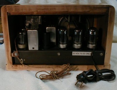
I built a 32-volt supply with items from my junk box that would deliver 32 volts at 1.5 amps. I plugged in the radio and it worked immediately (after I reversed the plug so that B+ was positive!) After alignment, the performance was excellent. The radio is very sensitive and the tone quality very good considering it only has a 5" PM speaker. This is amazing considering it only has 32 volts of B+ to work with.
This was a very interesting and challenging project. It would be nice to eventually find out what the original radio looked like, the IF frequency, construction of the antenna coil, etc. Here are some pictures of the completed radio. The knobs are from my junk box.
 |
 |
If anyone has any information on this radio or knows of another in existence, please let me know.
I was fortunate to acquire another Karola, this time an AC-DC version. There are the pictures.


Like in the 32 volt version, no model number or serial number was found.
Like the 32-volt version, this set also has 7 tubes (6 tubes plus ballast) and uses the identical chassis pan and cabinet. The RF and IF section is identical to the 32 volt version. The second detector/AVC/first audio is a 12SQ7 vs. an 12SR7 in the 32-volt section. This drives a 12A6 2nd audio. There is a 35Z5 rectifier. Of course, they could have used a 35L6 instead of a 12A6 and ballast! Makes one wonder! Maybe they wanted to fill up all the tube sockets, or maybe 12A6's were cheap.
The dial scale is the same as on the 32 volt version, and has the same odd error (55, 64, 60, etc). The dial pointer is different, so one of the radios likely has a replacement pointer. But also I have seen three different sets and all had different dial pointers.
The finish on the AC-DC set is a "photo finish" - a picture of wood. This is likely what the 32 volt set looked like originally. Perhaps someone though they would strip and refinish, only to find cheap wood under the "finish". On the other hand, another set I saw on eBay had yet a different finish.

I acquired another example of the AC/DC version discussed above. I installed the 32 volt chassis in this cabinet. So the AC/DC and 32 volt versions now look virtually identical, and the 32 volt version is likely close to the original appearance. I restored the extra AC/DC chassis, installed it in the refinished cabinet, and sold it on eBay.
The duplicate AC/DC set had a manufacturer's name stamped in red ink on the back: Brame Manufacturing, Minneapolis. But I was unable to find any useful information about this company. Google finds some hits on "Brame" and "Minneapolis" but nothing radio related.
I also acquired yet another Karola radio. This one was obviously 1950's vintage, using miniature tubes (but incorporating the same untuned IF stage as the AC/DC version). So the mystery deepens!
Here is an update on the Karola Corp courtesy Doug Miller:
Dear Douglas,
1946 is the first year that Karola Corp. appears in the city directory.
Robert C. Brame was the president of Karola Corp. located at 922 Washburn
Av. N. Karola was indeed a radio manufacturer. The vice-president was
Elmer Wendt and the secretary/treasurer was Arthur B. Reed. Hope this
helps!
Toni Miller
Librarian
Special Collections
Minneapolis Public Library
250 Marquette Ave S
Minneapolis, MN 55401
Dave McClellan
W6SQV
Atlanta, Georgia
Go Back
Home Page
Antique Radio Collection
Send email